RS232 over TCP thru WiFi USB/TTL serial Bridge 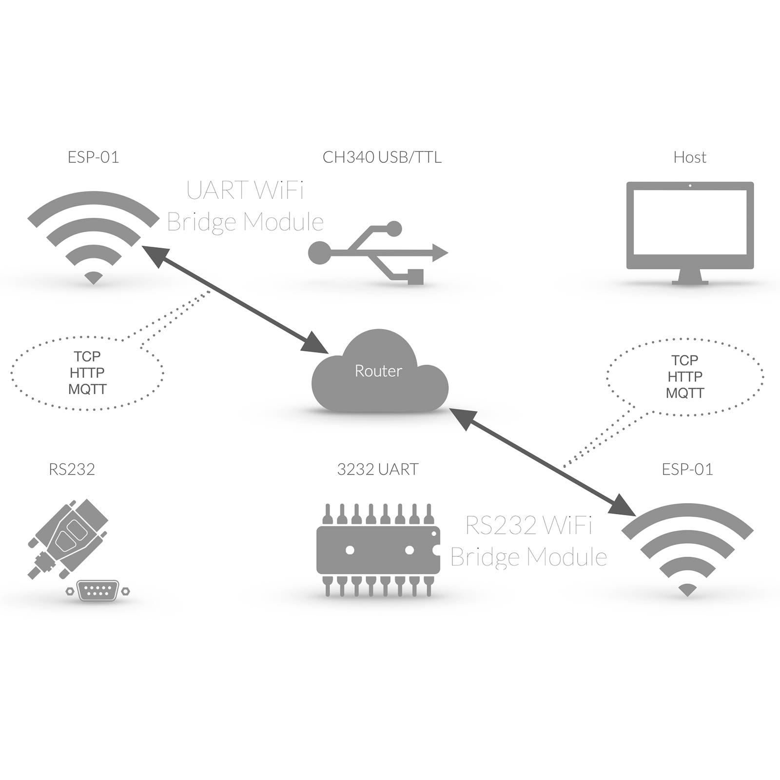 |
RS232 COM Schnittstelle
Die RS232 Schnittstelle hat ihren Ursprung in den 1960er Jahren und wird mittlerweile häufig durch den Universal Serial Bus ersetzt. Dementsprechend verfügen viele PC’s und auch Notebooks über keine physische RS232 Schnittstelle mehr, eine serielle Datenübertragung erfolgt meist über USB (Universal Serial Bus). Bei MAC’s ist generell keine RS232 / COM Schnittstelle mehr verfügbar. Da RS232 aber häufig zur Anbindung von Endgeräten Anwendung findet, bedarf es meist entsprechender RS232 / USB Konverter. Vorteil dieser kabelgebundenen RS232 Verbindung ist die Herstellung eines “physischen”, im Detail virtuellen COM Port. Der virtuelle COM Port wird dabei direkt in dem jeweiligen Betriebssystem bereitgestellt, bzw. kann direkt in einer Software angesprochen werden. Neben der kabelgebundenen RS232 Anbindung kann gleichermassen ein virtueller COM Port über WLan realisiert werden. Im nachfolgenden Tutorial wird mittels
Das USB WiFi Bridge Modul erfüllt dabei die Funktion eines virtuellen COM Port am Host und erfüllt sämtliche Rahmenbedingungen eines typischen RS232 Anschluss. Die grundlegenden Parameter einer WLan gebundenen COM Schnittstelle unterscheiden sich nicht im Vergleich zu einer kabelgebundenen RS232 Schnittstelle
Die seriellen Daten werden lediglich auf WLan umgesetzt und über TCP transferiert. Im Vorfeld muss zunächst die Basiskonfiguration des durchgeführt werden. Ferner muß nun noch die TCP UART Bridge am aktiviert (GPIO1 als TCP Tx und GPIO3 als TCP Rx konfiguriert) werden. Der Host Rechner verfügt nun über einen empfangsbereiten virtuellen COM Port. |
RS232 COM Interface
The RS232 COM Interface is a standard originally introduced in 1960 for serial communication transmission of data. Meanwhile most Computers are based on other serial Interface such as USB (Universal Serial Bus). Because of RS232 Standard often RS232 is used to connect Devices to Computers thru RS232 / USB Converter. Advantage of a wired RS232 connection is a “physical”, in Detail virtual COM Port. The virtual COM Port is directly available thru Operating System and is available in Software Applications. Besides the wired RS232 Connection, a virtual COM Port can be realized thru WiFi. In our tutorial we describe a RS232 Connection thru WiFi and a virtual COM Port
The USB WiFi Bridge Module enables full virtual COM Port functionality. The basic of serial Data transfer is based on same parameters such as regular / wired RS232 / COM Port serial connection.
The serial Data are just transferred thru TCP over WiFi. First step Module Basic Configuration After Basic Configuration of USB WiFi Bridge Module is finished TCP serial Bridge Mode of must be enabled (set GPIO1 to TCP Tx and GPIO3 to TCP Rx). The host computer now has a virtual COM port ready to receive. |
Tasmota TCP COM Port Configuration  |
Tasmota Konfigurieren
Nun muss das EI-OT Dual RS232 Modul noch entsprechend mittels der Tasmota Weboberfläche konfiguriert werden, sodass RS232 Signale direkt auf TCP umgesetzt werden. In diesem Beispiel wird die zweite RS232 Schnittstelle des EI-OT dual RS232 Moduls, also GPIO4 und GPIO5 verwendet und entsprechend innerhalb der Tasmota Firmware wie folgt konfiguriert:
|
Tasmota Configuration
Now the EI-OT Dual RS232 module must be configured accordingly using the Tasmota web interface so that RS232 signals are converted directly to TCP. In this example, the second RS232 interface of the EI-OT dual RS232 module, i.e. GPIO4 and GPIO5, is used and configured accordingly within the Tasmota firmware as follows:
|
RS232 Tasmota serial TCP COM Port Configuration  |
TCP COM Port Konfigurieren
Im Eigentlichen ist die Anbindung einer virtuellen COM Schnittstelle über WLan und Tasmota TCP Socket einer typischen COM Port Anbindung gleichzusetzen. Im Detail Bedarf es dabei der typischen Konfiguration der seriellen Schnittstelle die mittels Konsole und Kommandozeilen Eingabe wie folgt konfiguriert wird
Sobald die Verbindung erfolgreich hergestellt wurde, gibt die Konsole des USB WiFi Bridge Moduls Got connection from 192.168.178.71 aus. |
TCP COM Port COnfiguration
Compared to a regular COM Port connection there is no big difference to a Tasmota TCP Socket based COM Port connection. It requires also typical COM Port / Interface Parameter configuration such as
Soon as TCP Socket connection is active, in USB WiFi Bridge Console the message Got connection from 192.168.178.71 appears. |