
EI-OT 8 Channel Relays PRO Module Basic Setup Step by Step  |
Basis – Konfiguration
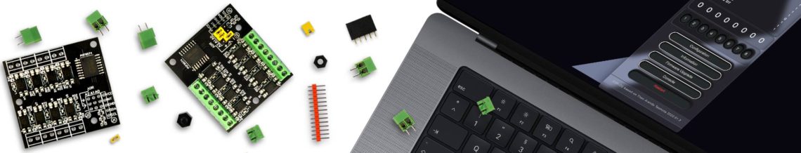
Mittels der ESP-OS Firmware erfolgt zunächst die Basiskonfiguration des EI-OT ESP8266 8 Kanal PRO Relais Moduls innerhalb von Sekunden. Die Basiskonfiguration bezieht sich im Detail auf den ESP8266 in Kombination mit dem PCF8574 im Detail die Konfiguration des I2C Bus. Die Basis Konfiguration des ESP8266 Schritt für Schritt:
Der ESP8266 wurde erfolgreich konfiguriert, die ESP-OS Standardkonfiguration Generic wurde auf EI-OT 8CH Relay PRO geändert. Auch der I2C Bus wurde bereits erfolgreich vorkonfiguriert, zu erkennen am ESP-OS Status Fenster und den dort aufgelisteten PCF8574-1 D0 bis D7 sowie dem zweiten PCF8574-2 D0 bis D7 Der PCF8574 ist ein typischer I/O Expander, zu Deutsch eine Ein- / Ausgang- Erweiterung. Aktuell sind alle Kanäle (D0 bis D7) beider PCF8574 als Eingang konfiguriert. |
Basic Configuration
With the ESP-OS Webinterface the Basic Configuration of the EI-OT ESP8266 8 Channel PRO Relays Module takes only view seconds. The Basic Configuration its based on the ESP8266 in combination with the PCF8574, in detail configuration of the I2C Bus. Basic Configuration of the ESP8266 Step by Step:
Also the I2C Bus is ready configured. According ESP-OS Status Window the PCF8574-1 Channels from D0 up to D7, also the second PCF8574-2 from D0 to D7. The PCF8574 is an I/O (INput / OUTput) Expander, actual I/O channels are set as Input. |
EI-OT 8 Channel Relays PRO Module Output Input configuration  |
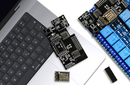
PCF8574 Konfiguration
Abschliessend müssen nun
konfiguriert werden. Zunächst gilt es den jeweiligen PCF8574 zu identifizieren. ESP-OS listet die PCF8574 aufsteigend anhand der I2C Adresse auf. Der PCF8574 des 8 Kanal Relais Moduls hat die Adresse 0x39, wurde dem PCF8574 Input Trigger Modul die I2C 0x38 Adresse zugewiesen, ist Device 1 = der PCF8574 des Input Trigger Moduls, andernfalls ist die Device 2 = der PCF8574 des Input Trigger Moduls. Im hier dargestellten Beispiel wurde dem Input Trigger Modul die I2C Adresse 0x3A zugewiesen, dementsprechend
Dementsprechend müssen die 8 Kanäle des Gerät 1 als Ausgang zum Schalten der 8 Relais konfiguriert werden
Das EI-OT ESP8266 8 Kanal Relais Modul wurde erfolgreich konfiguriert. Das Statusfenster zeigt nun die 8 Eingänge des PCF8574 Input Trigger Moduls. Sobald eine Benutzereingabe erfolgt, wechselt der Eingang seinen Status von 1 auf 0. Die Buttons 1 bis 8 stellen die 8 Relais dar. Durch einen Klick auf das jeweilige Relais lassen sich nun die 8 Relais mittels der ESP-OS Benutzeroberfläche schalten. Die Basiskonfiguration des EI-OT ESP8266 8 Kanal PRO Relais ist abgeschlossen. |
PCF8574 Configuration
To Finish the Configuration
Most important step is recognizing each PCF8574. ESP-OS is listing PCF8574 devices based on I2C address. I2C Address of the 8 Channel Relays Module is set to 0x39. If PCF8574 Input Trigger Module has I2C address 0x38, Device 1 = PCF8574 Input Trigger Module, otherwise PCF8574 Input Trigger Module = Device 2. In our example the PCF8574 Input Trigger Modules I2C is set to 0x3A, so Device 2 is Input Trigger Module. Based on that the 8 Output Channels for switching Relays must be configured as follows
After rebooting, the ESP-OS status window shows the 8 input channels of the PCF8574-2 Device. Soon as a input signal appears, channel status change from 1 to 0. The ESP-OS Interface indicates Buttons 1 to 8. Each button represent one of the 8 Relays. To toggle a Relay just click on the button. The Basic Configuration of the EI-OT ESP8266 8 Channel PRO Relays Module is finished. |
EI-OT 8 Channel Relays PRO Module Output Input configuration  |
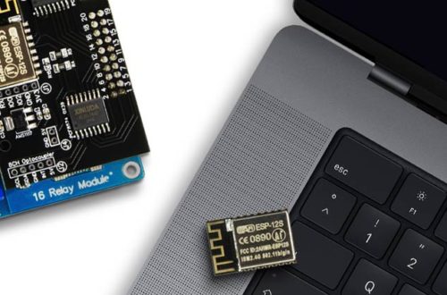
Regel Rule Konfiguration
Typischerweise verwendet man Eingangssignale Taster zur direkten Interaktion mit Relais
Hierzu bedient man sich einer einfacher Regel (Rule), im Detail hier nachzulesen. Eine einfache Regel um alle 8 Relais bei Betätigung des jeweiligen Tasters umzuschalten lautet Rule1 ON PCF8574-2_INP#D0=0 DO Power1 TOGGLE ENDON ON PCF8574-2_INP#D1=0 DO Power2 TOGGLE ENDON ON PCF8574-2_INP#D2=0 DO Power3 TOGGLE ENDON ON PCF8574-2_INP#D3=0 DO Power4 TOGGLE ENDON ON PCF8574-2_INP#D4=0 DO Power5 TOGGLE ENDON ON PCF8574-2_INP#D6=0 DO Power7 TOGGLE ENDON ON PCF8574-2_INP#D7=0 DO Power8 TOGGLE ENDON Diese Regel muss nun mittels Konsole gesetzt und aktiviert werden, hierzu in der ESP-OS Benutzeroberfläche
drückt man nun einen Taster wird gemäß der festgelegten Regel die jeweilige Routine ausgeführt, in Anlehnung an obiges Beispiel
Möchten man die Regel deaktivieren muss lediglich Rule1 0 in die Kommandozeile eigegeben und durch Drücken der Taster Enter übertragen werden. |
Rule Configuration
Normally an User Input should interacting with Relays
So all we need are a simple rule, details aboutrules you could find here. A simple Rule for toggle Relays soon as a button is active Rule1 ON PCF8574-2_INP#D0=0 DO Power1 TOGGLE ENDON ON PCF8574-2_INP#D1=0 DO Power2 TOGGLE ENDON ON PCF8574-2_INP#D2=0 DO Power3 TOGGLE ENDON ON PCF8574-2_INP#D3=0 DO Power4 TOGGLE ENDON ON PCF8574-2_INP#D4=0 DO Power5 TOGGLE ENDON ON PCF8574-2_INP#D6=0 DO Power7 TOGGLE ENDON ON PCF8574-2_INP#D7=0 DO Power8 TOGGLE ENDON This Rule must implemented thru Terminal / Console
The Module / PCF8574 Inputs are enabled, based on 4CH Pro Relays Example
To disable Rule1 just write Rule1 0 into command line and press ENTER key. |
5 Comments
Schubert
Hallo Team, ich benötige bitte ihre Hilfe.
Ich habe eine Tasmota DS18B20 AM2301 EI-OT ESP8266 gekauft und möchte gern die Temperaturdaten in ThingSpeak schreiben.
Welche Einstellungen muß ich in den MQTT-Einstellungen machen ?
Im Moment schreibt er in der Konsole „Verbindung fehlgeschlagen aufgrund von mqtt3.thingspeak.com:1883, rc 4“.
Vielen Dank für ihre Hilfe.
VG Heiko Schubert
admin
Hallo,
bin leider kein Thingspeak Anwender, aber
laut Konsole / Ausgabe Verbindung fehlgeschlagen aufgrund von mqtt3.thingspeak.com:1883, rc 4
verweist auf eine vom Server abgelehnte Verbindung aufgrund von falschen
MQTT Benutzername bzw. MQTT Passwort.
Grüße
Markus
Schubert
Hallo, ich habe es korrigiert.
MQT: Verbindungsversuch…
MQT: verbunden
MQT: channels/2775016/subscribe/fields/field1/temperature/LWT = Online (beibehalten)
MQT: channels/2775016/subscribe/fields/field1/temperature/cmnd/POWER =
MQT: abonniere channels/2775016/subscribe/fields/field1/temperature/cmnd/#
MQT: löse abo. von homeassistant/status
Jetzt verbindert er sich, aber was muß ich bei den MQTT Einstellungen bei topic = %topic% und full topic (%prefix%/%topic%/) eintragen, damit die Temperatur gesendet und von ThingSpeak empfangen wird ?
VD und VG
admin
eine Option wäre über die Konsole mittels Befehl FullTopic
basierend auf den Daten könnte das
FullTopic channels/2775016/publish//fields/field1/temperaturesein, eventuell kopieren und in die Befehlszeile der Konsole einfügen und die ENTER Taste drücken
das Modul sendet dann
channels/2775016/publish/fields/field1/temperature/SENSOR
eine Versuch ists wert
Markus
admin
Hallo Heiko,
ich tippe (wie bereits erwähnt bin kein ThinkSpeak, HomeAssistant, … Mix aus MQTT Broker / Client Anwender) mal auf den Eintrag full topic
fields/field1/temperature
wird aber nicht funktionieren denn
derzeit dürfte das Modul
über MQTT übertragen.
Üblicherweise passiert das Ganze ja umgekehrt,
notfalls lässt man sich sämtliche Topics durch Wildcard / # anzeigen.
Hier abonniert der Client eine vorgegebene Topic (wo auch immer die daher kommt),
das Ganze aufzudrösseln ist dann auf Seite von ThinkSpeak und da sind wir in dem Gedrössel aus Broker (Server) / Client.
Aus meiner Sicht sind die Einträge fields field1 Platzhalter die in ThinkSpeak nicht gesetzt wurden.
Bitte nicht falsch verstehen aber ich bin da im Blindflug, ich hoffe ich konnte trotzdem helfen.
Grüße
Markus