EI-OT INA226 ESP8266 Tasmota Modulbausatz 5-18V Bestückung und Konfiguration
Tasmota,  Tasmota INA226 Strom- Current- Sensor Modul 5-18V

Tasmota INA226 5-18V Stromsensor Modul konfigurieren

Tasmota INA226 Stromsensor Modul Konfiguration
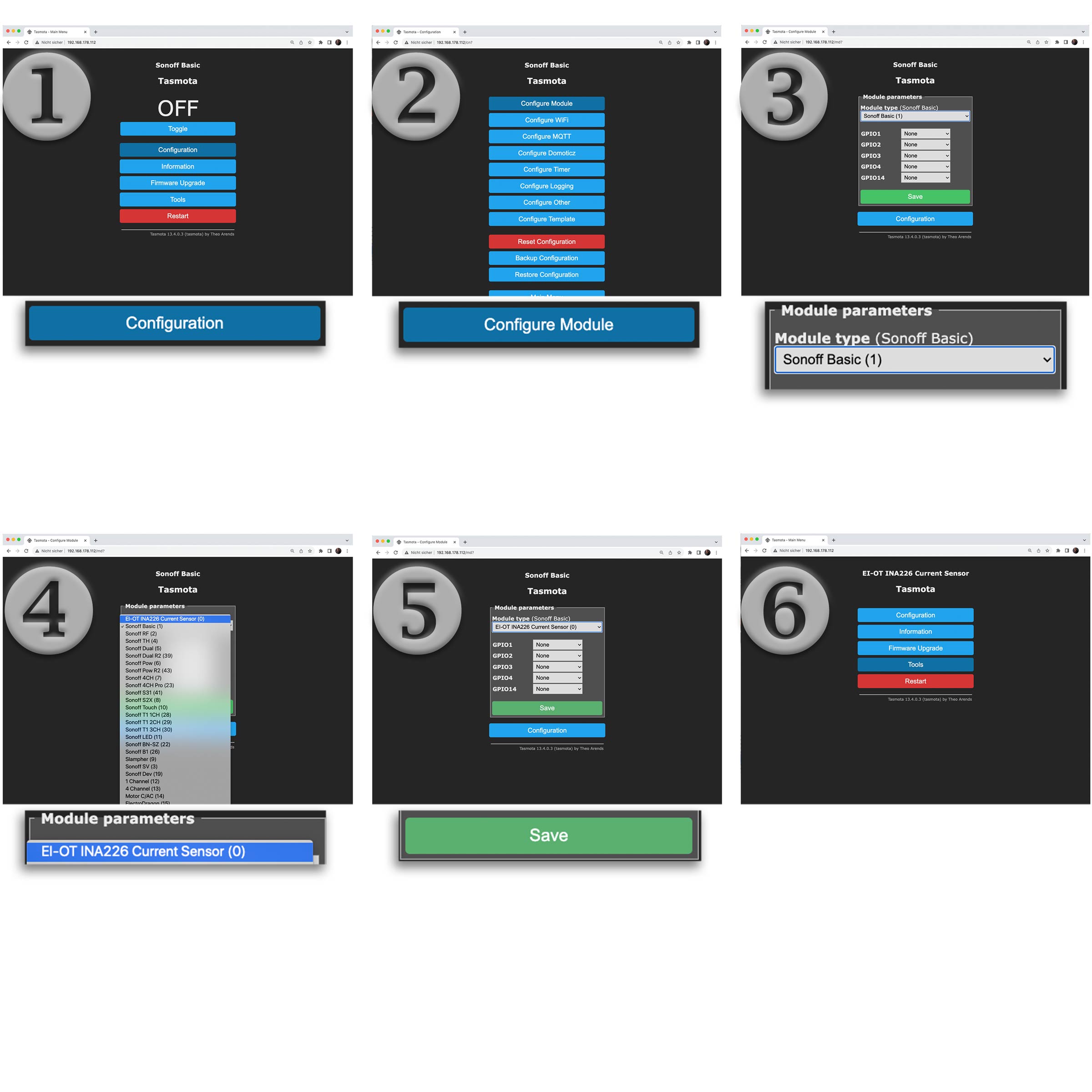
Tasmota Konfiguration

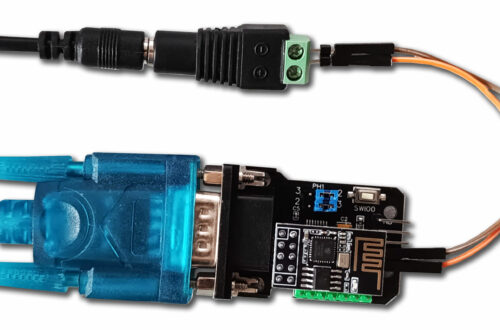
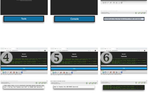
Die Tasmota Firmware wurde für das INA226 Modul angepasst und eigens kompiliert, im Detail wurde der INA226 I2C Sensor integriert und die GPIO’s über ein Tasmota Template entsprechend zugewiesen.

Nachdem das Tasmota INA226 Stromsensor Modul entsprechend im lokalen Netzwerk eingebunden wurde erfolgt die Basiskonfiguration wie folgt

  1. klicke im Tasmota Webinterface auf Configuration
  2. klicke im Konfigurationsmenü auf Configure Module
  3. klicke innerhalb der Module Parameter auf das Drop Down Module Type
  4. wähle EI-OT INA226 Current Sensor (0) aus
  5. klicke auf Save, das Tasmota Stromsensor Modul für einen Reboot aus
  6. nach dem erfolgreichen Reboot erscheint das EI-OT INA226 Current Sensor Webinterface (noch ohne Messwerte)
Tasmota Template

The Tasmota firmware was adapted and specially compiled for the INA226 module. The INA226 I2C sensor was integrated in detail and the GPIOs were assigned accordingly using a Tasmota template.

After the Tasmota INA226 current sensor module has been integrated into the local network, the basic configuration is as follows:

  1. click on Configuration in the Tasmota web interface
  2. click on Configure Module in the configuration menu
  3. click on the Module Type drop-down within the Module Parameters
  4. select EI-OT INA226 Current Sensor (0)
  5. click on Save to reboot the Tasmota current sensor module
  6. After the successful reboot, the EI-OT INA226 Current Sensor web interface appears (still without INA226 values)
Tasmota INA226 Stromsensor Skalierung
INA226 Skalierung

Das INA226 Stromsensor Modul ist in verschiedenen Version / Leistungsbereichen verfügbar. Je nach Ausführung und Leistung muß dementsprechend die jeweilige Skalierung mittels der Tasmota Konsole wie folgt durchgeführt werden:

  1. klicke im Tasmota Webinterface auf Tools
  2. im Tasmota Tools Menü klicke auf Console
  3. die Tasmota Console verfügt über ein Fenster zur Ausgabe von Statusmeldung sowie eine Kommandozeile zur Eingabe von spezifischen Tasmota Kommandos
  4. basierend auf der jeweiligen Version 2A 5A 10A oder 16A  sowie der I2C Adresse des INA 226 muss nun der Text / das Tasmota Kommando in die Befehlszeile eingegeben werden. Das jeweilige Kommando basierend auf Version und I2C Adresse ist hier in der Tabelle hinterlegt (siehe unten), lediglich das jeweilige Kommando kopieren und in die Tasmota Kommandozeile einfügen. Um da Tasmota Kommando auszuführen muß abschliessend die ENTER Taste gedrückt werden.
  5. die INA226 Skalierung wird dann innerhalb der Tasmota Firmware gesetzt, ferner wird ein reboot ausgeführt und die aktuellen Messwerte des INA226 Sensors in der Konsole ausgegeben
  6. wechselt man in das Hauptmenü werden nun die aktuellen Strom-, Spannung- und Leistungs- Wert im Tasmota Webinterface ausgegeben
INA226 Skalierung

The INA226 current sensor module is available in different versions / performance ranges. Depending on the version and performance, the respective scaling must be configured using the Tasmota console as follows:

  1. click on Tools in the Tasmota web interface
  2. in the Tasmota Tools menu click on Console
  3. hhe Tasmota Console has a window for outputting status messages also a command line for entering specific Tasmota commands
  4. Based on the respective version 2A 5A 10A or 16A and the I2C address of the INA226 Sensor, the text / Tasmota command must now be entered into the command line.  The respective command based on version and I2C address is stored here in the table (see below), just copy the respective command and paste it into the Tasmota command line. To execute the Tasmota command, you must then press the ENTER key.
  5. the INA226 scaling is then set within the Tasmota firmware, a reboot is carried out and the current measured values ​​of the INA226 sensor are output in the console window.
  6. if you switch to the main menu, the current, voltage and power values ​​are now displayed in the Tasmota web interface

Version
I2C Addr.
Tasmota Command
2A 0x40 Backlog VoltRes 3; WattRes 3; Sensor54 11 0.04; Sensor54 12 2.04; Sensor54 2
5A 0x40 Backlog VoltRes 3; WattRes 3; Sensor54 11 0.15; Sensor54 12 5.46; Sensor54 2
10A 0x40 Backlog VoltRes 3; WattRes 3; Sensor54 11 0.008; Sensor54 12 10.24; Sensor54 2
16A 0x40 Backlog VoltRes 3; WattRes 3; Sensor54 11 0.008; Sensor54 12 10.24; Sensor54 2
2A 0x41 Backlog VoltRes 3; WattRes 3; Sensor54 21 0.04; Sensor54 22 2.04; Sensor54 2
5A 0x41 Backlog VoltRes 3; WattRes 3; Sensor54 21 0.15; Sensor54 22 5.46; Sensor54 2
10A 0x41 Backlog VoltRes 3; WattRes 3; Sensor54 21 0.008; Sensor54 22 10.24; Sensor54 2
16A 0x41 Backlog VoltRes 3; WattRes 3; Sensor54 21 0.005; Sensor54 22 16.38; Sensor54 2
2A 0x44 Backlog VoltRes 3; WattRes 3; Sensor54 31 0.04; Sensor54 32 2.04; Sensor54 2
5A 0x44 Backlog VoltRes 3; WattRes 3; Sensor54 31 0.15; Sensor54 32 5.46; Sensor54 2
10A 0x44 Backlog VoltRes 3; WattRes 3; Sensor54 31 0.008; Sensor54 32 10.24; Sensor54 2
16A 0x44 Backlog VoltRes 3; WattRes 3; Sensor54 31 0.005; Sensor54 32 16.38; Sensor54 2
2A 0x45 Backlog VoltRes 3; WattRes 3; Sensor54 41 0.04; Sensor54 42 2.04; Sensor54 2
5A 0x45 Backlog VoltRes 3; WattRes 3; Sensor54 41 0.15; Sensor54 42 5.46; Sensor54 2
10A 0x45 Backlog VoltRes 3; WattRes 3; Sensor54 41 0.008; Sensor54 42 10.24; Sensor54 2
16A 0x45 Backlog VoltRes 3; WattRes 3; Sensor54 41 0.005; Sensor54 42 16.38; Sensor54 2

Schreibe einen Kommentar

Deine E-Mail-Adresse wird nicht veröffentlicht. Erforderliche Felder sind mit * markiert