EI-OT RS485 ESP8266 Tasmota config
RS485 Module

EI-OT RS485 WLan Bridge Modul 5-12V Zusammenbau

EI-OT RS485 WiFi Bridge Module Board assembling
EI-OT RS485 WLan Bridge Modul bestücken

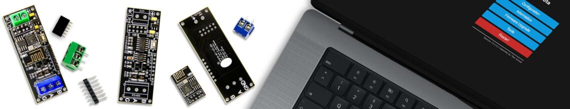
Das EI-OT Tasmota RS485 WLan Bridge Modul ist bereits mit SMD Komponenten wie

  • AMS1117 3,3V Spannungskonverter nebst Kondensatoren
  • Widerständen
  • SP3485EN RS485 UART Konverter
  • 74HC04D Inverter IC
  • Reset Taster
  • SMD Sicherungen
  • Dioden
  • LED’s

bestückt.

Zur Inbetriebnahme müssen lediglich, nachfolgende Komponenten wie in nebenstehender Grafik dargestellt bestückt / verlötet werden.

Die Bestückung des RS485 WLan Bridge Moduls Schritt für Schritt:

  1. Platziere den 2×5 Pin Stecksockel auf H1 und verlöte die Pins auf der Rückseite
  2. Platziere die 7-polige Pinleiste auf H2 und verlöte die Pins auf der Rückseite
  3. Platziere die 2-polige Schraubklemme auf VCC und verlöte die Pins auf der Rückseite
  4. Platziere die 3-polige Schraubklemme auf RS485 und verlöte die Pins auf der Rückseite

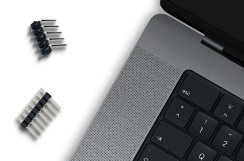
Das RS485 WLan Bridge Modul ist fertig bestückt.

EI-OT RS485 WiFi Bridge Module assembling

The EI-OT RS485 WiFi Bridge Module is already equipped with SMD components such as

  • AMS1117 3.3V Voltage Converter and capacitors
  • Resistors
  • SP3485EN RS485 UART Converter
  • 74HC04D Inverter IC
  • Reset Button
  • SMD Fuses
  • Diodes
  • LED’s

For completion, the following components simply need to be assembled.

The assembly of the EI-OT RS485 WiFi Bridge Module step by step:

  1. Place the 2×5 pin socket on H1 and solder the pins on the bottom side
  2. Place the 7-pin header on H2 and solder the pins on the bottom side
  3. Place the 2-pin  screw terminal on VCC and solder the pins on the bottom side
  4. Place the 3-pin  screw terminal on RS485 and solder the pins on the bottom side

The basic assembling of the RS485 WiFi Bridge Module is finished.

Schreibe einen Kommentar

Deine E-Mail-Adresse wird nicht veröffentlicht. Erforderliche Felder sind mit * markiert