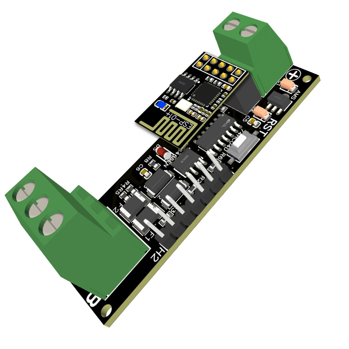
EI-OT RS485 WiFi Bridge Module 5-12V Module connection  |
Spannungsversorgung
Die Spannungsversorgung des RS485 WiFi Bridge Modul erfolgt über die 2-polige Schraubklemme
Zur Spannungsversorgung eignet sich sowohl ein typisches Steckernetzteil als auch jedwede Gleichspannung im Bereich von 5-12V mit 200mA. |
Power Supply
The RS485 WiFi Bridge module is supplied with power via the 2-pin screw terminal
Both a typical plug-in power supply and any DC voltage in the range of 5-12V with 200mA are suitable for power supply. |
EI-OT ESP-01+ ESP8266 RS485 Module connection  |
RS485 Anschluss
Die RS485 Bus Anbindung erfolgt über die 3-polige Schraubklemme
|
RS485 Connection
The RS485 bus connection is made via the 3-pin screw terminal
|


4 Comments
Oliver Lomberg
Guten Morgen.
Ich habe einen Holley dtz541 zdba Stromzähler. Leider ist die LED zu schwach für einen Lesekopf. Der Zähler besitzt aber die RS485 Schnittstelle. Kann ich mit dem EI-OT RS485 WiFi Bridge Modul den Zähler auslesen? Der Zähler hat kein GND. Ist das ein Problem? Welchen Kabelquerschnitt muss ich für den Anschluss verwenden?
Vielen Dank.
Gruss
O. Lomberg
admin
Hallo,
habe gerade einmal in das Manual vom dtz541 zdba Stromzähler bezüglich des RS485 Anschluss nachgeblättert,
also der „fehlende“ GND ist kein Problem, bzw. trifft es häufig zu, daß keine GND Klemme am Endgerät bereitgestellt wird.
Bezüglich des Kabelquerschnitt, kommt natürlich auf die Länge der Kabelanbindung an üblicherweise sollte es aber mindestens 0,25 Quadrat sein.
Das passende Script gibt es auf Tasmota GitHub
https://tasmota.github.io/docs/Smart-Meter-Interface/#holley-dtz541-sml
Andreas Becker
Hallo,
gerne wüßte ich, ob das Tasmota RS485 Modul mit einem Growatt SPH BH-UP kommuniziert ( modbus RTU / TCP).
Es wäre prima, wenn das Modul Daten übermittelt, die sich dann z.B. über HomeAssistant darstellen lassen.
admin
Hallo Andreas,
also für Tasmota wird derzeit noch kein fertiges Script angeboten <-- denke auch nicht dass Du das benötigst. Ich habe gerade einmal bezüglich Home Assistant recherchiert, hier gibt es eine entsprechende Integration für Growatt. Mit einfachen Worten
Selbstredend muss im Vorfeld HA Growatt Integration entsprechend installiert worden sein
dort muss (wenn ich mich richtig erinnere entsprechen TCP 502 Port und Modbus RTU konfiguriert werden
Grüße
Markus