|
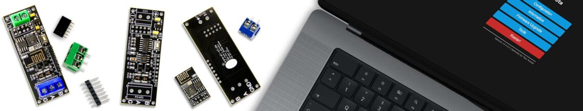
Tasmota Konfiguration
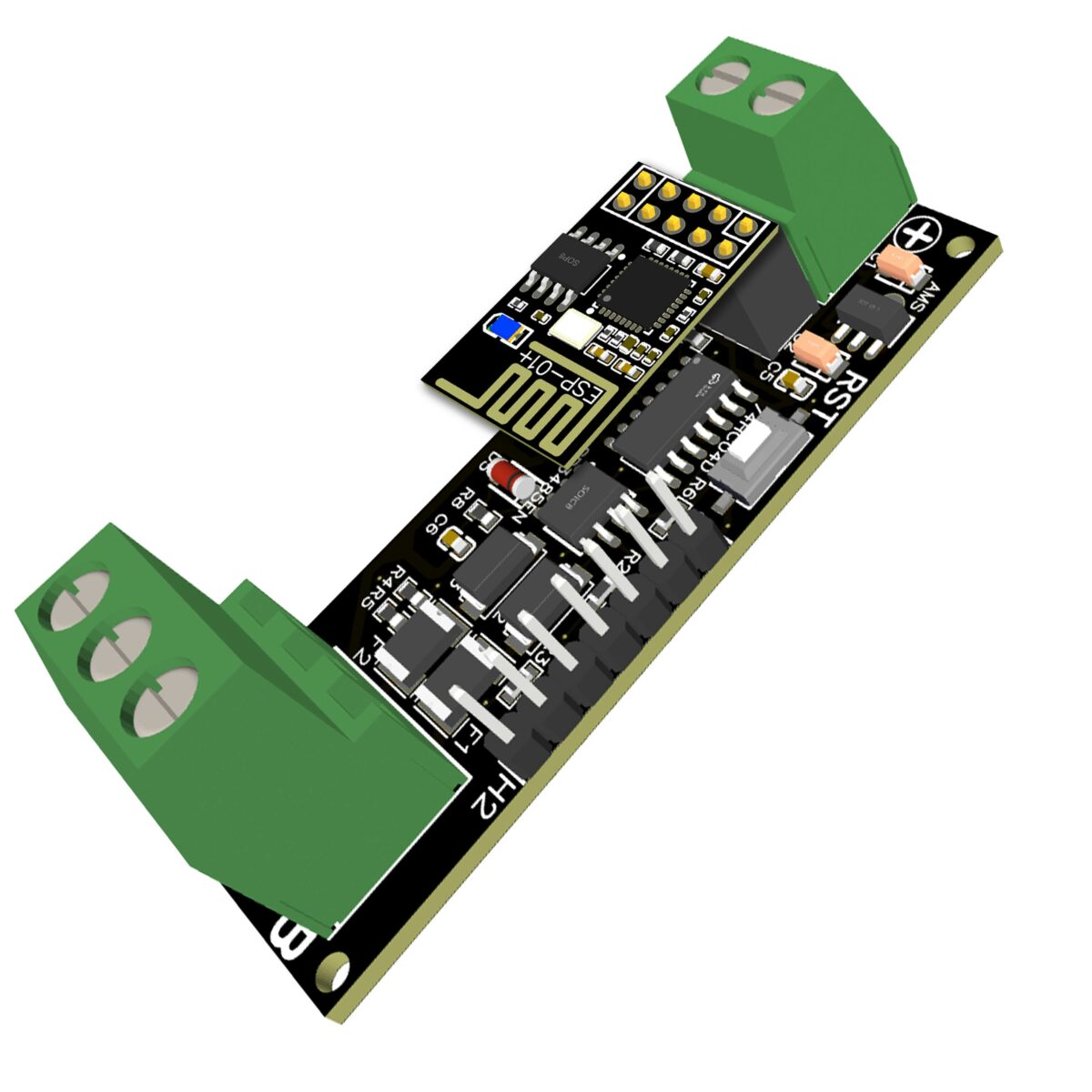
Der grundlegende Aufbau des RS485 WiFi Bridge Modul basiert auf dem SP3485EN in Kombination mit dem 74HC04. Im Detail wird dabei lediglich das RS485 Signal, bzw. der RS485 Level auf den UART Level des ESP8266 umgesetzt. Dabei wurde
gemäß der standardmässigen Konfiguration des ESP8266 verwendet, diesbezüglich ist im Eigentlichen keine weitere Konfiguration notwendig. Neben GPIO1 und GPIO3 verfügt das EI-OT RS485 WiFi Bridge Modul über folgende auf die 7-polige Pinleiste ausgeführte GPIO’s
|
Tasmota Configuration
The basic structure of the RS485 WiFi Bridge Module is based on the SP3485EN in combination with the 74HC04. In detail, just the RS485 signal or lets say the RS485 level is converted to the UART level of the ESP8266 serial interface. This was done
used according to the standard configuration of the ESP8266, no further configuration is actually necessary in this regard. In addition to GPIO1 and GPIO3, the EI-OT RS485 WiFi Bridge module has the following GPIOs on the 7-pin pin strip
|
|
|
Modbus Konfiguration
Modbus ist ein typische Kommunikationsprotokoll zwischen Master und Slaves basierend auf
Die Tasmota Firmware verfügt über eine Vielzahl an integrierten Modbus Protokollen basierend auf Endgeräten bzw. Standards, zur Aktivierung muß GPIO1 TX und GPIO3 RX entsprechend konfiguriert werden.
Aufgrund abweichender Geräteversion und / oder Firmware Version Änderungen können Änderungen im jeweiligen Protokoll vorliegen, hier sei auf die jeweilige Tasmota- bzw. Hersteller- Dokumentation verwiesen. |
Modbus Configuration
Modbus is a typical communication protocol based on master and slaves
The Tasmota firmware has a variety of integrated Modbus protocols based on end devices or standards; for activation, GPIO1 TX and GPIO3 RX must be configured accordingly
Due to different device and/or firmware versions, there may be changes in the respective protocol; please refer to the respective Tasmota or manufacturer documentation. |
|