|
serielle Kommunikation
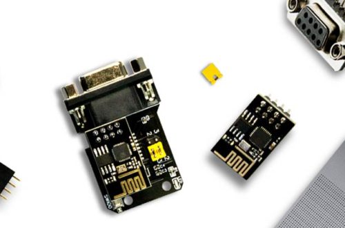
Zwar unterstützt die Tasmota Firmware eine Vielzahl von RS485 basierenden Protokollen, reduziert auf die Hardware erfolgt aber stets eine Umsetzung des RS485 Level auf die serielle UART Schnittstelle des ESP8266. Dementsprechend kann eine direkte Kommunikation, beispielsweise über die Tasmota Console erfolgen. Im folgenden RS485 WLan Bridge Beispiel wird ein typischer USB RS485 Konverter direkt mit dem EI-OT RS485 verbunden:
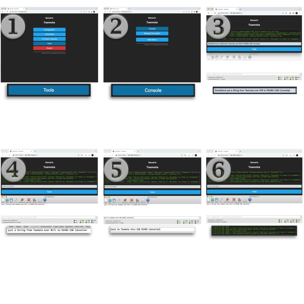
Im Bezug des PC / MAC wird ferner ein typisches serial terminal Programm (Roger Meiers Cool Term) verwendet. Im eigentlichen Bedarf es keiner großen Einstellungen, lediglich die Baudrate des seriellen Terminals muß auf 115200 b/s (Tasmota Firmware Standard Baudrate) gesetzt werden. Ferner sollte der Line Modus (Befehlszeilen Modus) im Terminal Programm aktiviert sein. |
serial Communication
Although the Tasmota firmware supports a variety of RS485-based protocols. But reduced to the hardware / basic function, the RS485 level is always converted to 3.3V UART level transmitted thru serial UART interface of the ESP8266. Accordingly, direct communication can take place, for example via the Tasmota Console. In the following RS485 WiFi Bridge example, a typical USB RS485 converter is connected directly to the EI-OT RS485:
A typical serial terminal program (Roger Meier’s Cool Term) is also used for the PC / MAC. In actual fact, no major settings are required, only the baud rate of the serial terminal must be set to 115200 b/s (Tasmota firmware standard baud rate). |
EI-OT ESP8266 RS232 RX TX serial Bridge Configuration  |
RS485 WLan Beispiel
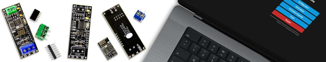
Nachdem wie oben beschrieben eine entsprechende Verbindung zwischen RS485 USB Konverter und dem RS485 WLan Bridge Modul hergestellt wurde, kann auch schon mit direkten WLan RS485 Kommunikation begonnen werden.
In Anlehnung an die Tasmota Firmware, im Detail serial commands sowie in Kombination mit Tasmota Rules kann jedwede individuelle Lösung zur Herstellung einer individuellen RS485 WLan Bridge herbeigeführt werden. |
RS485 WiFi Example
After a connection between the RS485 USB converter and the RS485 WLan bridge module has been established (as described above), a WiFi RS485 WiFi brdige communication can begin.
Based on the Tasmota firmware, in detail serial commands and / or in combination with Tasmota Rules, any solution can be created to create an individual RS485 WLan bridge. |