EI-OT INA226 ESP8266 Tasmota Modulbausatz 5-18V Bestückung und Konfiguration
Tasmota INA226 Strom- Current- Sensor Modul 5-18V

EI-OT INA226 Stromsensor Modul 5-18V Inbetriebnahme Jumper Setting

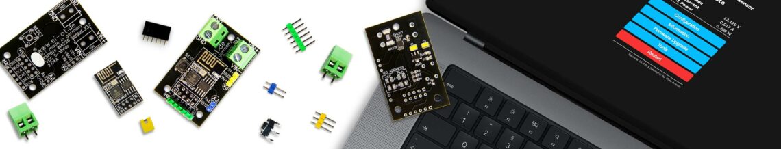
EI-OT ESP-01+ ESP8266 INA226 5-18V Jumper setting
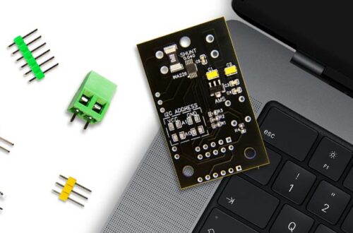
EI-OT 5-18V Stromsensor  Jumper Setting

Das EI-OT INA226 5-18V Modul verfügt über 2 Jumperleisten

AJ Alarm Jumper verfügt über den Pin

  • ALE = Alarmausgang des INA226, ist im Betrieb auf HIGH / 3,3V+, wird der vorgegebene maximale Strom überschritten wechselt der Level des ALE PIN auf LOW. Bitte beachten die Alarm Funktion des INA226 wird innerhalb der Tasmota Firmware NICHT unterstützt, dementsprechend keinen Jumper setzen um eine Verbindung zu GPIO12 herzustellen!
  • GPIO12 des ESP8266 ESP-01+ Moduls

VJ Bus Voltage Jumper verfügt über die Pins

  • VBUS = der Bus Voltage Pin des INA226 Sensors zur Erfassung der jeweiligen Buss Spannung
  • VIN- = die Spannung die am jeweiligen Shunt Widerstand anliegt
  • VIN+ = die Versorgungsspannung, eigentlich Bus Spannung

Mittels Jumper kann somit selektiert werden welche Spannung auf den Bus Voltage Pin des INA226 geleitet wird.

EI-OT 5-18V Current Sensor Jumper Setting

The EI-OT INA226 5-18V module has 2 jumper strips

AJ Alarm Jumper has the pin

  • ALE = alarm output of the INA226, is at HIGH / 3.3V+ during operation, if the specified maximum current is exceeded, the level of the ALE PIN changes to LOW. Please note the alarm function of the INA226 is NOT supported within the Tasmota firmware, DONT USE JUMPER to close connection to GPIO12!
  • GPIO12 of the ESP8266 ESP-01+ module

VJ Bus Voltage Jumper has the pins

  • VBUS = the bus voltage pin of the INA226 sensor for recording the respective bus voltage
  • VIN- = the voltage present at the respective shunt resistor
  • VIN+ = the supply voltage, actually bus voltage

Using jumper you can select which voltage is routed to the bus voltage pin of the INA226.

EI-OT ESP-01+ ESP8266 INA226 5-18V Inbetriebnahme
EI-OT 5-18V Stromsensor  Inbetriebnahme

Nachdem das EI-OT Stromsensor Modul

  • bestückt wurde
  • I2C Adressierung durchgeführt wurde
  • VJ Jumper gesetzt wurde

muss lediglich das ESP-01+ Modul auf den Stecksockel platziert werden.

Abschliessend kann nun der Anschluss des EI-OT 5-18V Stromsensor Moduls erfolgen.

EI-OT 5-18V Current Sensor Installation

After the EI-OT current sensor module

  • was assembled
  • I2C addressing was carried out
  • VJ Jumper was set

place the ESP-01+ module on the socket.

Finally, the EI-OT 5-18V current sensor module can now be connected.

Schreibe einen Kommentar

Deine E-Mail-Adresse wird nicht veröffentlicht. Erforderliche Felder sind mit * markiert