
EI-OT 8 Channel I2C PC817 Optocoupler Module assembling 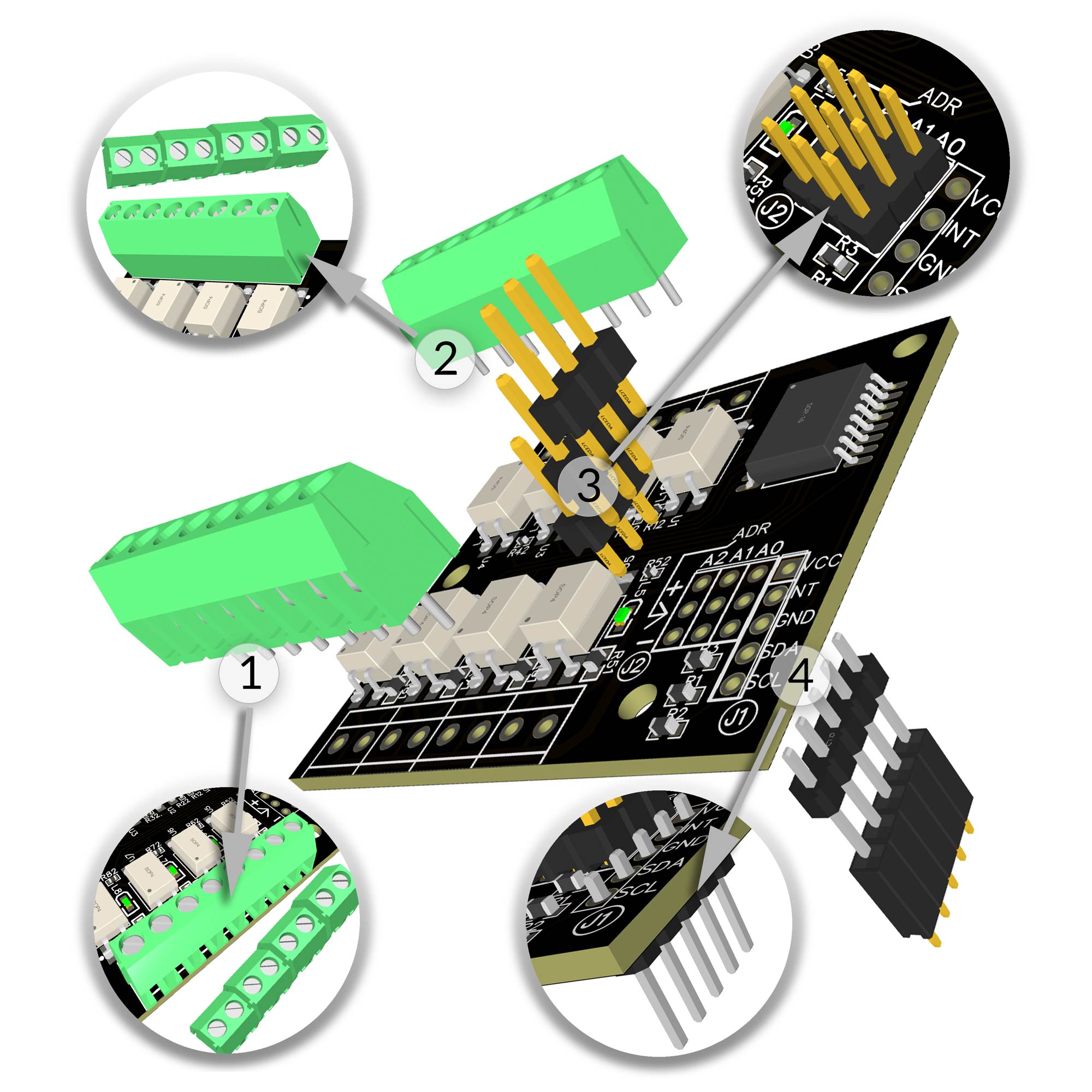 |
Zusammenbau / Bestückung
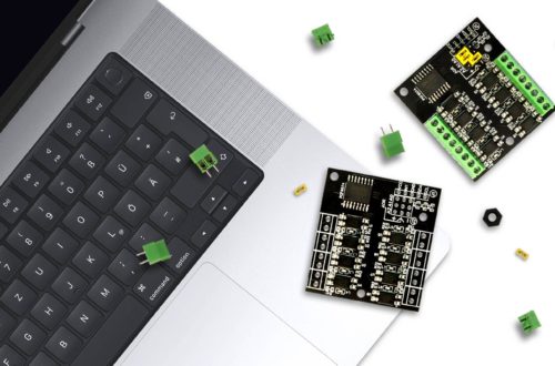
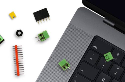
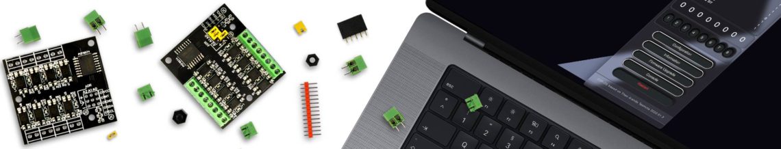
Das EI-OT 8 Kanal PC817 Optokoppler Input Trigger PRO Modul ist bereits mit SMD Komponenten bestückt. Zur Inbetriebnahme müssen nachfolgende Komponenten wie in nebenstehender Grafik (zum Vergrößern auf das Bild klicken) bestückt / verlötet werden Die Bestückung des EI-OT 8 Kanal PCF8574 Input Trigger Modul Schritt für Schritt:
Das EI-OT 8 Kanal I2C Input Trigger Modul ist fertig bestückt, sodass im nächsten Schritt die I2C Adressierung erfolgen kann. |
Assembling
Besides the SMD components, the EI-OT 8 Channel PCF8574 Input Trigger Module requires additional components. Assembling of the EI-OT 8 Channel PCF8574 Input Trigger Module Step by Step:
The basic assembling of the EI-OT 8 Channel I2C Input Module is finished, for next step I2C address configuration. |
PCF8574A I2C Adresses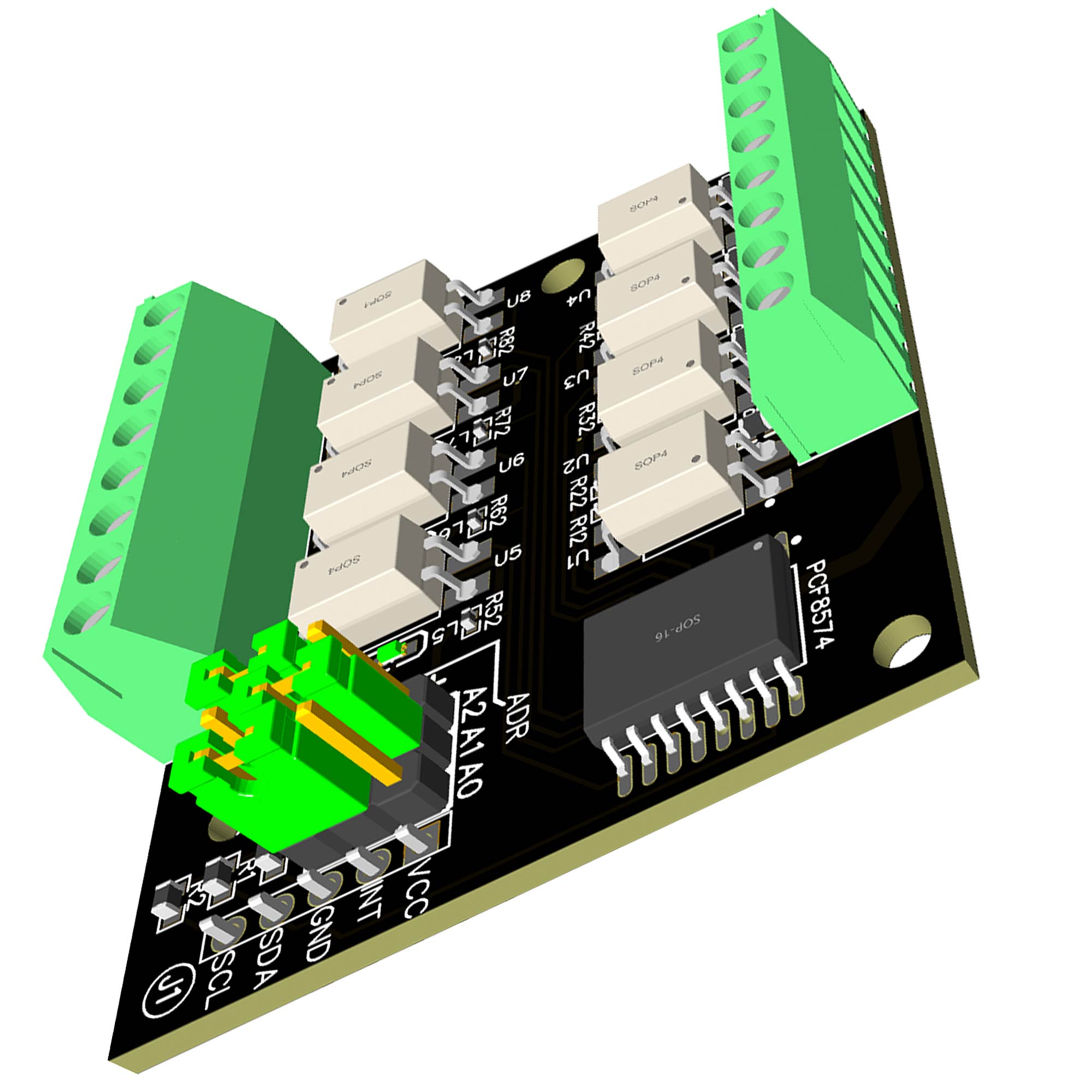 |
PCF8574 I2C Adresse
Der PCF8574 IC ist in 2 Varianten verfügbar
Dementsprechend können bis zu 8 Stück PC8574 und 8 Stück PCF8574A, also insgesamt bis zu 16 PCF8574 an nur einem I2C Bus betrieben werden. Grundlage bildet dabei die I2C Adressierung, jeder PCF8574 benötigt eine eindeutige I2C Adresse innerhalb des I2C Bus, sodass die MCU (ESP8266) jeden einzelnen PCF8574 IC ansprechen kann. Im Bezug der EI-OT Module verwenden wir den PCF8574A, also den Adressbereich von 0x38 bis 0x3F Dementsprechend muss beim PCF8574 PC817 Optokoppler Modul in Kombination mit anderen Modulen wie dem
darauf geachtet werden, dass kein Konflikt bei der Konfiguration der I2C auftritt. An dieser Stelle sei erwähnt, im Vergleich zu ESP-OS unterstütz Tasmota weder die Adresse 0x27 des PCF8574 noch die 0x38 des PCF8574A. |
PCF8574 I2C Address
The PCF8574 is available in 2 versions
Based on I2C Address range up to 8 pcs. of PCF8574 and also 8 pcs. PCF8574A, in total 16 pcs. could be operated on just 1 I2C Bus. But every PCF8574 must have a unique I2C Address, so MCU (ESP8266) can establish a connection to each PCF8574 thru I2C Bus. For our EI-OT Module we use PCF8574A Version, in Detail we use 0x38 to 0x3F I2C Address Range. A specially in combination with the
those addresses could not be used. Compared to ESP-OS, Tasmota supports not PCF8574 address 0x27 also PCF8574A address 0x38. |
PCF8574 0x38 IC2 Address Jumper settings  |
I2C Adressierung mittels Jumper
Die I2C Addressierung des PCF8574A erfolgt mittels J2 und der 3 Jumper. I2C Adresse 0x38 Jumper A0 geschlossen mit – / GND Hinweis: |
I2C Addresses Jumper Settings
The I2C Addressing with 3 Jumpers on J2 I2C Address 0x38 Jumper A0 connected to – / GND Note: |
PCF8574 0x39 IC2 Address Jumper settings |
I2C Adresse 0x39
Jumper A0 geschlossen mit + / VCC Hinweis: |
I2C Address 0x39
Jumper A0 connected to + / VCC Note: |
PCF8574 0x3A IC2 Address Jumper settings |
I2C Adresse 0x3A
Jumper A0 geschlossen mit – / GND Hinweis: |
I2C Address 0x3A
Jumper A0 connected to – / GND Note: |
PCF8574 0x3B IC2 Address Jumper settings |
I2C Adresse 0x3B
Jumper A0 geschlossen mit + / VCC |
I2C Address 0x3B
Jumper A0 connected to + / VCC |
PCF8574 0x3C IC2 Address Jumper settings |
I2C Adresse 0x3C
Jumper A0 geschlossen mit – / GND |
I2C Address 0x3C
Jumper A0 connected to – / GND |
PCF8574 0x3D IC2 Address Jumper settings |
I2C Adresse 0x3D
Jumper A0 geschlossen mit + / VCC |
I2C Address 0x3D
Jumper A0 connected to + / VCC |
PCF8574 0x3E IC2 Address Jumper settings |
I2C Adresse 0x3E
Jumper A0 geschlossen mit – / GND |
I2C Address 0x3E
Jumper A0 connected to – / GND |
PCF8574 0x3F IC2 Address Jumper settings |
I2C Adresse 0x3F
Jumper A0 geschlossen mit + / VCC |
I2C Address 0x3F
Jumper A0 connected to + / VCC |