Assembling EI-OT PCB and Standard 16 Channel Relays Module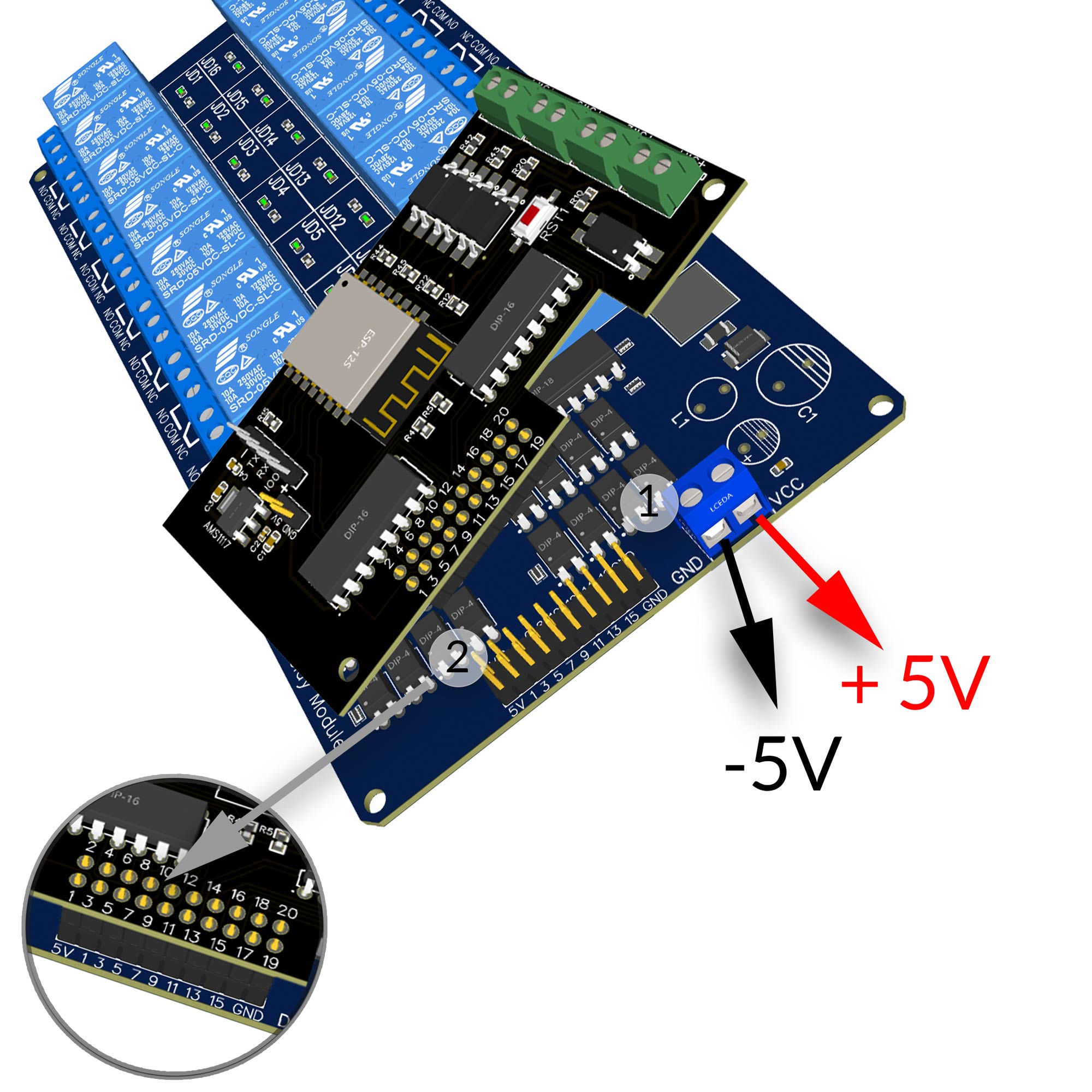 |
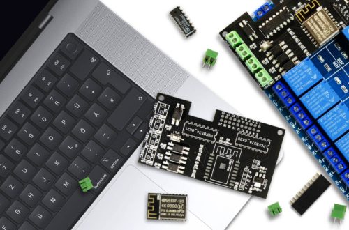
Spannungsversorgung
Sobald die Platine fertig bestückt wurde und die 2 Brücken zur Relais Spannungsversorgung gesetzt wurden, können Steuerungsplatine und das 16 Kanal Standard Relais Modul zusammengesetzt werden.
Das EI-OT 16 Kanal Standard Relais ist nun einsatzbereit. |
Power Supply
Soon as the PCB is assembled and the 2 connections for the 5V 16 Channel Standard Relays Module is connected, the controller PCB and the Relays Module can be assembled.
The EI-OT 16 Channel Standard Relays Module is finished. |
EI-OT 16 Channel Standard Relays Module Input Trigger 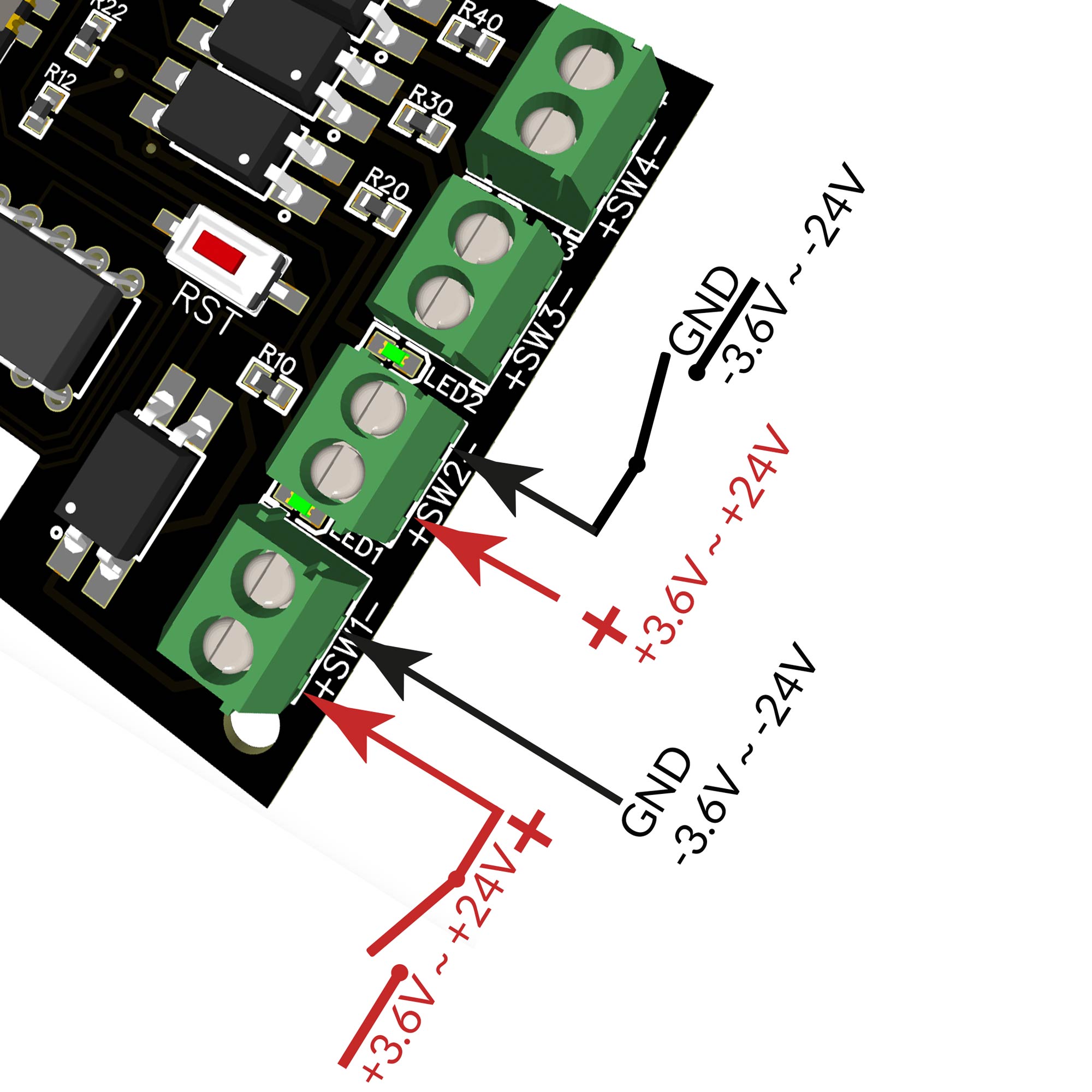 |
Eingangssignale
Das EI-OT ESP8266 16 Kanal Standard Relais Modul verfügt über 4 Stück mittels Optokoppler isolierte Eingänge. Die jeweilige Eingangsspannung muss im Bereich von 3,6V bis 24V liegen. Die Eingangsspannung kann für jeden Kanal (SW1 bis SW4) abweichend sein. Ferner kann sowohl LOW Level geschaltet nebenstehend als Beispiel SW4, also GND wird über einen Taster oder Schalter geschaltet und + (Plus) wird direkt auf die + Klemme geführt oder HIGH Level geschaltet nebenstehend als Beispiel SW2, also + Plus wird über einen Taster oder Schalter geschaltet und – (GND) wird direkt auf die – Klemme geführt. |
Trigger Input
Die EI-OT ESP8266 16 Channel Standard Relays Module has 4 pcs. optoisolated input trigger. The input voltage range must be between 3.6V up to 24V. Each channel supports different voltage, so input voltage must not have same voltage. Both input Signal could be used LOW Level switch (SW4) – GND is connected to a Button or Switch and + VCC is directly connected to + pole of screw connector or HIGH Level switch (SW2) + VCC is connected to a Button or Switch and – GND is directly connected to – pole of screw connector. |