Smart Home WLan 16 Kanal Standard Relais Bausatz
16 Kanal Standard

EI-OT ESP-07S 16 Kanal Standard Relais Modul Bestücken und Zusammenbau

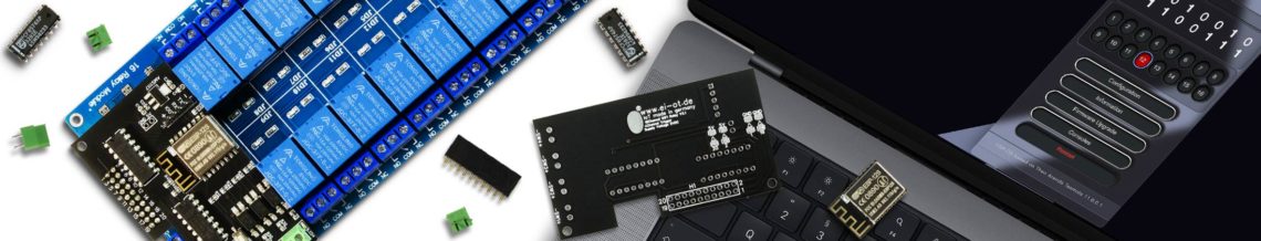
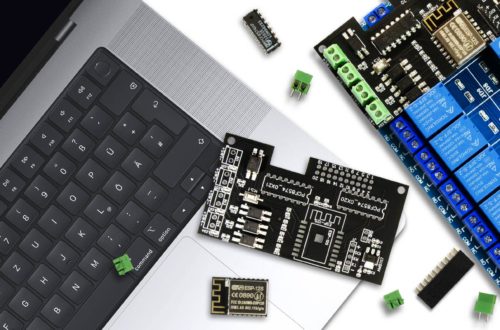
EI-OT 16 Channel ESP-07S 5V Relays Module assembling
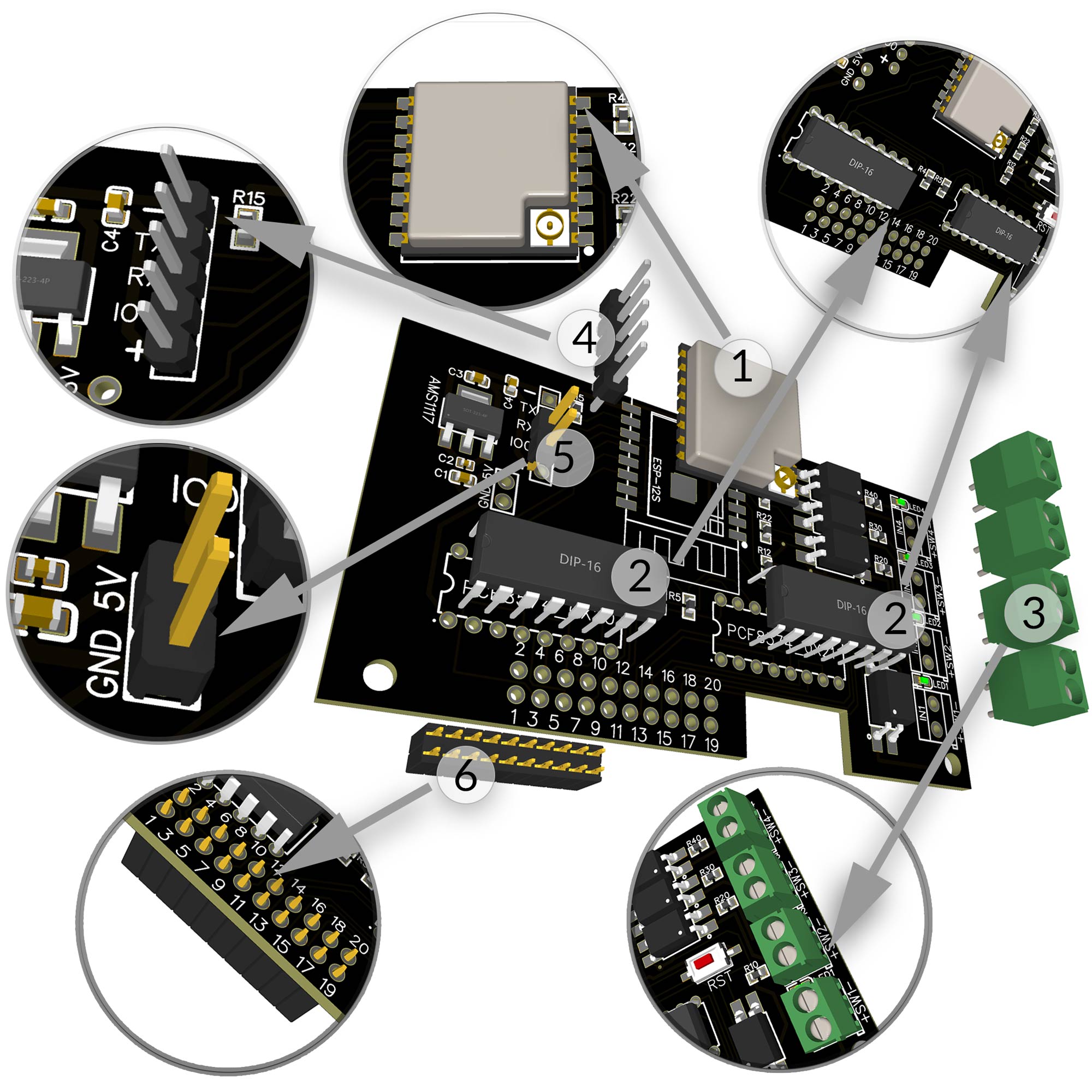
Zusammenbau / Bestückung

Das EI-OT ESP8266 16 Kanal ESP-07S Relais Modul ist bereits mit SMD Komponenten bestückt. Zur Inbetriebnahme müssen nachfolgende Komponenten wie in nebenstehender Grafik (zum Vergrößern auf das Bild klicken) bestückt / verlötet werden

Die Bestückung des EI-OT 16 Kanal ESP-07S Standard Relais Modul Schritt für Schritt:

  1. Das ESP8266 ESP-07S Modul entsprechend platzieren, am besten mit einem Clip, z.B. Wäscheklammer fixieren und verlöten
  2. Die 2 PCF8574 DIP16 IC jeweils auf der Platine platzieren (Pins durchstecken), dabei auf die Auskerbung des PCF8574 achten und die 16 Pins auf der Rückseite der Platine verlöten
  3. Jeweils eine der 4 Stück der 2-poligen KF350 Schraubklemmen  von IN1 bis IN4 auf der Platine platzieren / durchstecken und die Pins auf der Rückseite verlöten.
  4. Die 5-polige Pinleiste auf auf der Platine platzieren / durchstecken und auf der Rückseite verlöten
  5. Die 2-polige Pinleiste platzieren / durchstecken und auf der Rückseite verlöten
  6. Den 20-poligen Stecksockel von unten auf der Platine platzieren und auf der Oberseite der Platine verlöten

Das EI-OT 16 Kanal ESP-07S Standard Relais ist fertig bestückt, sodass im nächsten Schritt die notwendigen Verbindungen zum Betrieb des 5V 16 Kanal Relais Modul hergestellt werden können.

Assembling

Besides the SMD components, the EI-OT 16 Channel ESP-07S Relays Module requires additional components.

Assembling of the 16 Channel Relays Module Step by Step:

  1. Place the ESP8266 ESP-07S Module in correct direction on PCB, fix it with a clip or clothes peg and solder it
  2. Put each of the 2  PC8574 DIP16 IC in correct direction (pay attention of notch) on the PCB and solder the 16 Pins from backside
  3. Put the 2-pole KF350 Screw Connector  on the PCB (IN1 to IN4) and solder the  Pins from backside
  4. Put the 5-pole Pinheader on PCB and solder the Pins from backside
  5. Put the 2-pole Pinheader on PCB and solder the Pins from backside
  6. Assemble the 20-pole socket from bottom side of the PCB and solder the 20 Pins on PCB top side

The basic assembling of the EI-OT 16 Channel ESP-07S Standard Relays Module is finished.

5V Standard ESP-07S 16 Channel Relays Module Power Supply
Relais Spannungsversorgung

Die 5V Spannungsversorgung des EI-OT 16 Kanal Standard Relais erfolgt zentral durch den Schraubklemmen – Anschluß der blauen 16 Kanal Relais Platine.

Da aber 5V Relais Module sich in der Spannungsversorgung unterscheiden können, muss die Versorgungsspannung auf der Unterseite der EI-OT 16 Kanal Relais Platine entsprechend gebrückt werden.

Es sind 2 Versionen von 5V 16 Kanal Relais Modulen verfügbar

Version1:
der 5V PIN ist PIN 1 und PIN 2 (ganz links auf der 20 poligen Pinleiste)
der GND PIN ist PIN 19 und PIN 20 (ganz rechts auf der 20-poligen Pinleiste)

Hier muss auf der Unterseite der EI-OT 16 Kanal Standard Relais Platine
von 2 > 5V
und
von 19 > GND
gebrückt werden

Version2:
der GND PIN ist PIN 1 und PIN2   (ganz links auf der 20 poligen Pinleiste)
der VCC PIN ist PIN 19 und Pin 20 (ganz rechts auf der 20-poligen Pinleiste)

Hier muss auf der Unterseite der EI-OT 8 Kanal Standard Relais Platine
von 1 > GND
und
von 20 > 5V
gebrückt werden

Die Spannungsversorgung des 5V ESP-07S 16 Kanal Relais Moduls ist fertiggestellt.

Relays Power Supply

The Power Supply of the Relays is supported thru the 2-pole screw connector of the blue Relays Module Board.

The power supply of 5V Standard Relays Module could be different. In this regard the Voltage Supply must be connected on backside of EI-OT 16 Channel Module PCB.

There are 2 types of 5V 16 Channel Standard Relays Module available

Version1:
the VCC PIN is PIN 1 and PIN 2 (left side of the 20-pole Pinheader)
the GND PIN is PIN 19 and PIN 20 (right side of the 20-pole Pinheader)

please connect 2 > 5V Pads
and
connect 19 > GND Pads
n Bootom Side of the EI-OT 16 Channel Standard Relais Board

Version2:
the GND PIN is PIN 1 and PIN 2 (left side of the 20-pole Pinheader)
the VCC PIN is PIN 19 and PIN 20 (right side of the 20-pole Pinheader)

please connect 1 > GND Pads 
and
connect 20 > 5 Pads
n Bootom Side of the EI-OT 16 Channel Standard Relais Board

The Power Supply of the 5V ESP-07S 16 Channel Relays Module is finished.

Assembling EI-OT ESP-07S PCB and Standard 16 Channel Relays Module
Relais Modul verbinden

Sobald die Platine fertig bestückt wurde und die 2 Brücken zur Relais Spannungsversorgung gesetzt wurden, können Steuerungsplatine und das 16 Kanal Standard Relais Modul zusammengesetzt werden.

  1. Im ersten Schritt muss die  Spannungsversorgung mit einem entsprechenden 5V Gleichspannungsnetzteil hergestellt werden
    VCC = +5V
    GND = -5V
    Um die benötigte Leistung zum Betrieb der 16 Relais bereitzustellen, sollte das Netzteil mindestens 1500mA bereitstellen.
  2. stecke die 20-polige Buchse der EI-OT 16 Kanal Standard Relais Platine auf die 20-polige Pinleiste des blauen 5V 16 Kanal Relais Modul

Das EI-OT 16 Kanal ESP-07S Standard Relais ist nun einsatzbereit.

Relays Module Connection

Soon as the PCB is assembled and the 2 connections for the 5V 16 Channel Standard Relays Module is connected, the controller PCB and the Relays Module can be assembled.

  1. connect 5V Power Supply to 2-pole screw connector of blue Relays Module Board
    VCC = +5V
    GND = -5V
    The 16 Channel 5V Relays Module requires at least 1500mA.
  2. put the 20-pole Socket of the EI-OT 16 Channel PCB of the 20-pole Pinheader of the blue 5V 8 Channel Standard Relays Module

The EI-OT 16 Channel ESP-07S Standard Relays Module is finished.

Schreibe einen Kommentar

Deine E-Mail-Adresse wird nicht veröffentlicht. Erforderliche Felder sind mit * markiert