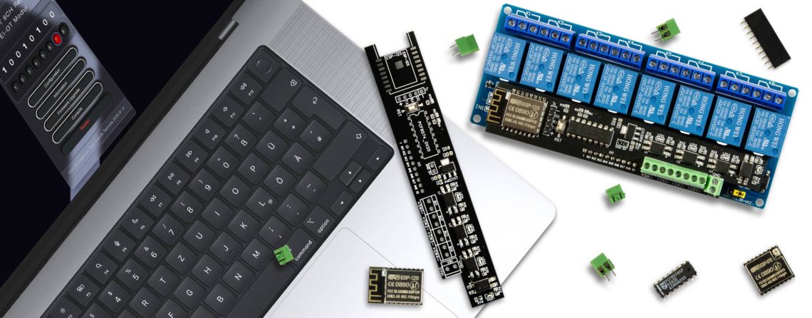
EI-OT 8 Channel Standard Relays Module connections  |
Spannungsversorgung
Die EI-OT ESP8266 8 Kanal Standard Relais Platine versorgt das 5V 8 Kanal Standard Relais Modul mit Spannung, diesbezüglich dürfen stets nur 5VDC (5V Gleichspannung) angeschlossen werden. Die Spannungsversorgung erfolgt mittels KF350 Schraubklemme, Anschluss
Als Netzteil eignen sich typische
Die Spannungsquelle sollte mindestens 700mA bereitstellen um ausreichende Leistung für die Relaisspulen bereitzustellen. Eingangssignale
Das EI-OT ESP8266 8 Kanal Standard Relais Modul verfügt über 4 Stück mittels Optokoppler isolierte Eingänge. Die jeweilige Eingangsspannung muss im Bereich von 3,6V bis 24V liegen. Die Eingangsspannung kann für jeden Kanal (SW1 bis SW4) abweichend sein. Ferner kann sowohl LOW Level geschaltet nebenstehend als Beispiel SW4, also GND wird über einen Taster oder Schalter geschaltet und + (Plus) wird direkt auf die + Klemme geführt oder HIGH Level geschaltet nebenstehend als Beispiel SW2, also + Plus wird über einen Taster oder Schalter geschaltet und – (GND) wird direkt auf die – Klemme geführt. |
Power Supply
The EI-OT ESP8266 8 Channel Standard Relays Board supports the 5V 8 Channel Standard Relays Board with Power. Based on the 5V Relays please use only 5 VDC Power Supply, otherwise the Relays will be damaged. Connect Power Supply thru KF350 Screw Connector
Typical Power Supplies are
The minimum Current should be 700mA. Trigger Input
Die EI-OT ESP8266 8 Channel Standard Relays Module has 4 pcs. optoisolated input trigger. The input voltage range must be between 3.6V up to 24V. Each channel supports different voltage, so input voltage must not have same voltage. Both input Signal could be used LOW Level switch (SW4) – GND is connected to a Button or Switch and + VCC is directly connected to + pole of screw connector or HIGH Level switch (SW2) + VCC is connected to a Button or Switch and – GND is directly connected to – pole of screw connector. |