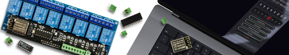
EI-OT 8 Channel Relays Module assembling  |
Das EI-OT ESP8266 8 Kanal Relais Modul ist bereits mit SMD Komponenten bestückt. Zur Inbetriebnahme müssen nachfolgende Komponenten wie in nebenstehender Grafik (zum Vergrößern auf das Bild klicken) bestückt / verlötet werden
Die Bestückung des EI-OT 8 Kanal Standard Relais Modul Schritt für Schritt:
- Auf die Lötpads für den ESP8266 entsprechend Lötpaste auftragen, oder falls nicht zur Hand vorverzinnen. Das ESP8266 Modul entsprechend platzieren, am besten mit einem Clip, z.B. Wäscheklammer fixieren und verlöten
- Den PCF8574 DIP16 IC auf der Platine platzieren (Pins durchstecken), dabei auf die Auskerbung des PCF8574 achten und die 16 Pins auf der Rückseite der Platine verlöten
- 4 Stück der 2-poligen KF350 Schraubklemmen zusammenstecken und von IN1 bis IN4 auf der Platine platzieren / durchstecken und die 8 Pins auf der Rückseite verlöten.
- Die fünfte 2-polige KF350 Schraubklemme auf VIN platzieren / durchstecken und auf der Rückseite verlöten
- Die 5-polige Pinleiste auf J1 platzieren / durchstecken und auf der Rückseite verlöten
- Die 2-polige Pinleiste platzieren / durchstecken und auf der Rückseite verlöten
- Den 10-poligen Stecksockel von unten auf der Platine platzieren und auf der Oberseite der Platine verlöten
Das EI-OT 8 Kanal Standard Relais ist fertig bestückt, sodass im nächsten Schritt die notwendigen Verbindungen zum Betrieb des 5V 8 Kanal Relais Modul hergestellt werden können. |
Besides the SMD components, the EI-OT 8 Channel Relays Module requires additional components.
Assembling of the 8 Channel Relays Module Step by Step:
- Put solder paste on the ESP8266 solder pads, if not available pre-tin the ESP8266 pads. Put the ESP8266 Module in correct direction on position, fix it with a clip or clothes peg and solder it.
- Put the PC8574 DIP16 IC in correct direction (pay attention of notch) on the PCB and solder the 16 Pins from backside
- Assemble 4 pcs. of 2-pole KF350 Screw Connector to a 8 pole connector. Put it on the PCB (IN1 to IN4) and solder the 8 Pins from backside
- Put the fifth 2-pole KF350 Screw connector on VIN and solder the 2 Pins from backside
- Put the 5-pole Pinheader on J1 and solder the Pins from backside
- Put the 2-pole Pinheader on PCB and solder the Pins from backside
- Assemble the 10-pole socket from bottom side of the PCB and solder the 10 Pins on PCB top side
The basic assembling of the EI-OT 8 Channel Standard Relays Module is finished. |
5V Standard Relays Module Power Supply  |
Die 5V Spannungsversorgung des EI-OT 8 Kanal Standard Relais erfolgt zentral durch die Steuerungsplatine.
Da aber 5V Relais Module sich in der Spannungsversorgung unterscheiden können, muss die Versorgungsspannung der Relais auf der Unterseite der EI-OT 8 Kanal Relais Platine entsprechend gebrückt werden.
Es sind 2 Versionen von 5V 8 Kanal Relais Modulen verfügbar
Version1:
der VCC PIN ist PIN 1 (ganz links auf der 10 poligen Pinleiste)
der GND PIN ist PIN 10 (ganz rechts auf der 10-poligen Pinleiste)
Hier muss auf der Unterseite der EI-OT 8 Kanal Standard Relais Platine
von 5V > 1
und
von GND > 10
gebrückt werden
Version2:
der GND PIN ist PIN 1 (ganz links auf der 10 poligen Pinleiste)
der VCC PIN ist PIN 10 (ganz rechts auf der 10-poligen Pinleiste)
Hier muss auf der Unterseite der EI-OT 8 Kanal Standard Relais Platine
von GND > 1
und
von 5V > 1
gebrückt werden
Die Spannungsversorgung des 5V 8 Kanal Relais Moduls ist fertiggestellt. |
The Power Supply of the Relays is supported thru the controller PCB.
The power supply of 5V Standard Relays Module could be different. In this regard the Relais Voltage Supply must be connected on backside of EI-OT 8 Channel Module PCB.
There are 2 types of 5V 8 Channel Standard Relays Module available
Version1:
the VCC PIN is PIN 1 (left side of the 10-pole Pinheader)
the GND PIN is PIN 10 (right side of the 10-pole Pinheader)
please connect 5V > 1 Pads
and
connect GND > 10 Pads
n Bootom Side of the EI-OT 8 Channel Standard Relais Board
Version2:
the GND PIN is PIN 1 (left side of the 10-pole Pinheader)
the VCC PIN is PIN 10 (right side of the 10-pole Pinheader)
please connect GND > 1 Pads
and
connect 5V > 10 Pads
n Bootom Side of the EI-OT 8 Channel Standard Relais Board
The Power Supply of the 5V 8 Channel Relays Module is finished. |
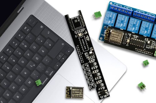
Assembling EI-OT PCB and Standard 8 Channel Relays Module |
Sobald die Platine fertig bestückt wurde und die 2 Brücken zur Relais Spannungsversorgung gesetzt wurden, können Steuerungsplatine und das 8 Kanal Standard Relais Modul zusammengesetzt werden.
- stecke die 10-polige Buchse der EI-OT 8 Kanal Standard Relais Platine auf die 10-polige Pinleiste des 5V 8 Kanal Standard Relais Modul
- das 5V 8 Kanal Standard Relais unterstützt sowohl LOW als auch HIGH Level Aktivierung, da wir LOW Level schalten, muss der Jumper bezüglich der Spannungsversorgung der Relais auf VCC > JD-VCC gesetzt werden.
Das EI-OT 8 Kanal Standard Relais ist nun einsatzbereit. |
Soon as the PCB is assembled and the 2 connections for the 5V 8 Channel Standard Relays Module is connected, the controller PCB and the Relays Module can be assembled.
- put the 10-pole Socket of the EI-OT 8 Channel PCB of the 10-pole Pinheader of the 5V 8 Channel Standard Relays Module
- the 5V 8 Channel Standard Relays Module supports LOW and HIGH Level signal. We need LOW Level switching, so Jumper must connect VCC to JD-VCC.
The EI-OT 8 Channel Standard Relays Module is finished. |