Beschreibung

EI-OT ESP8266 ESP-07S 4 Kanal Standard Relais Modulbausatz |
||||
|
ähnliche Produkte
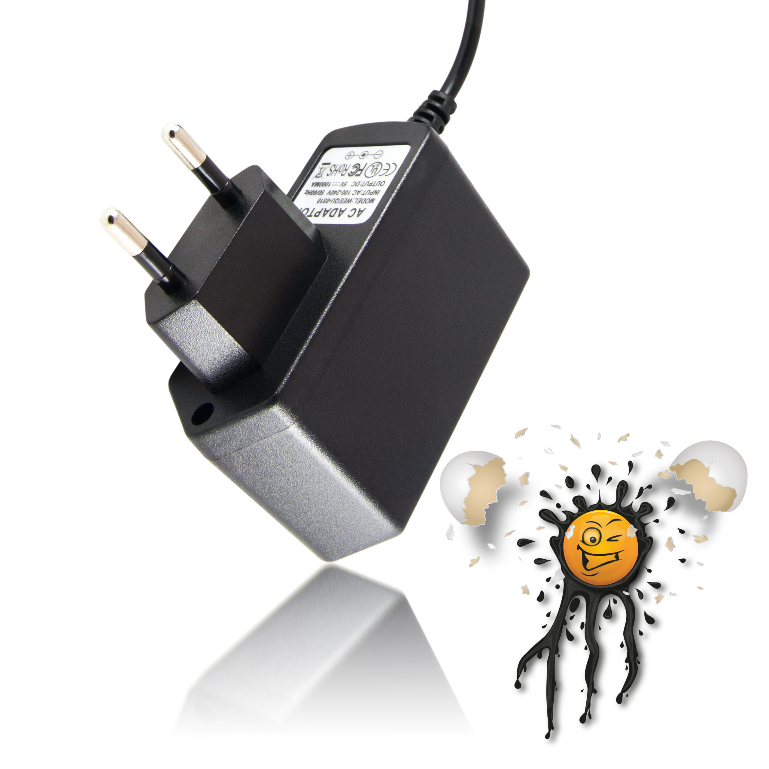
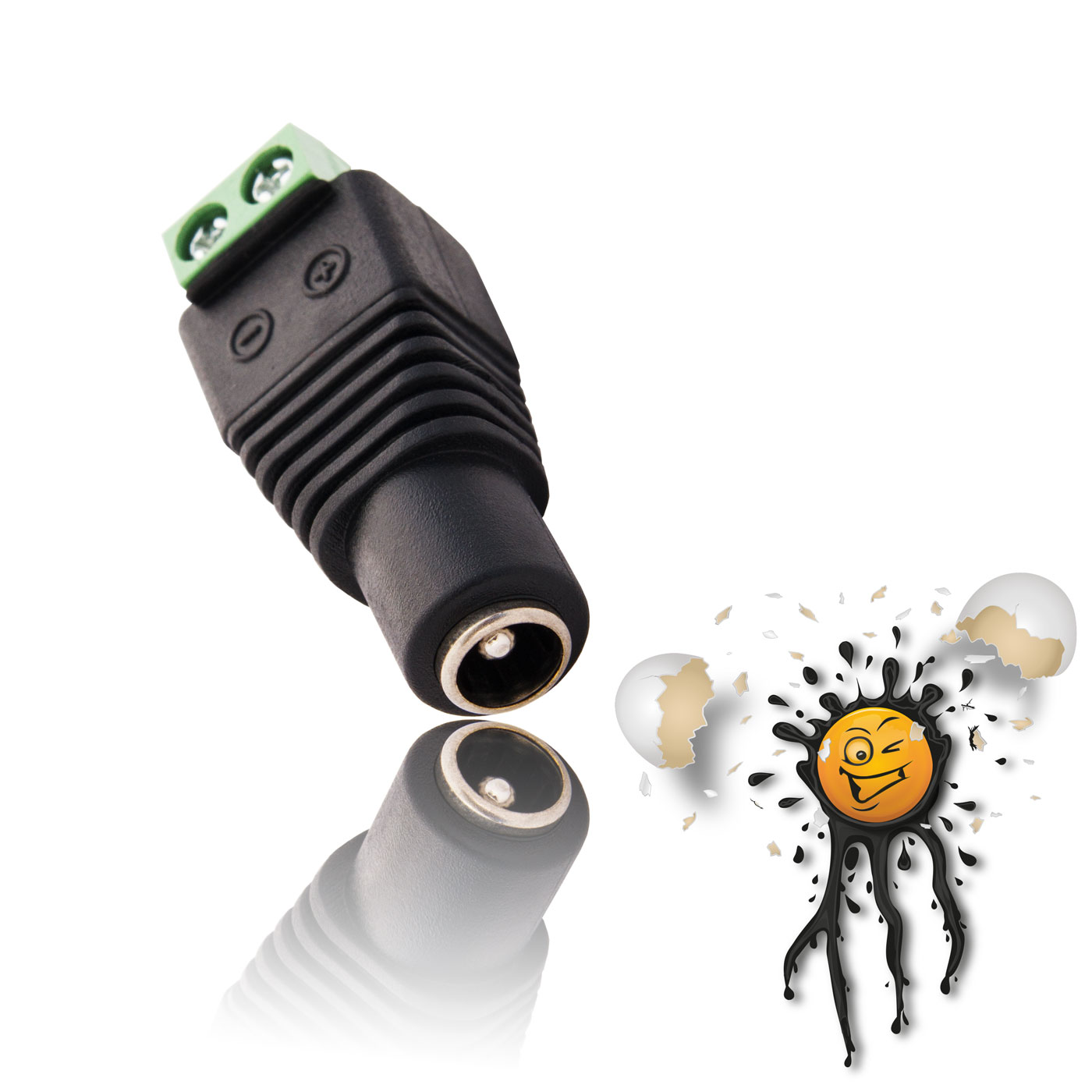
related items Spannungsversorgung
Power Supply Antennen
Antennas Zubehör
Accessoires |
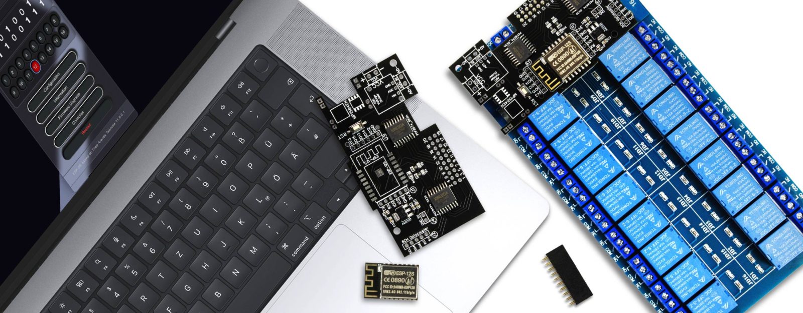
Das EI-OT ESP-07S 4 Kanal Standard Relais Modul eignet sich als WLan Schaltzentrale für Smart Home Anwendungen und schaltet bis zu 4 Geräte (Relais). Das EI-OT ESP8266 4 Kanal Standard Relais Modul mit dem AI Thinker ESP8266 ESP-07S zum Anschluss einer externen Antenne über I-PEX Anschluss. Das ESP-07S 4 Kanal Standard Relais Modul eignet sich für den Einsatz bei größerer Funkstrecken. In Kombination mit einer entsprechenden Antenne wird die Reichweite des ESP8266 entsprechend erhöht und optimiert. Der ESP8266 ESP-07S verfügt über einen 32Mbit SPI Flash Speicher und erlaubt eine einfache Smart Home Integration in lokale / private Heimnetzwerke. Die 4 Relais des EI-OT ESP-07S 4 Kanal Relais Board werden über
in Kombination mit einem N-Kanal Transistor geschaltet. Diesbezüglich gilt zu beachten, dass bei der Spannungsversorgung, bzw. während des Bootvorgangs des ESP8266, alle 4 Relais des 4 Kanal Standard Relais Modul kurzfristig (ca. 1 Sekunde) aktiviert werden. Die Ei-OT ESP-07S 4 Kanal Steuerungsplatine ist passend für typische 5V 4 Kanal Relais Module und wird einfach über die 6-polige Pinleiste des Relais Moduls verbunden / aufgesteckt. Dabei bedarf es keiner gesonderten Spannungsversorgung, die Spannungsversorgung erfolgt zentral über die 2-polige Anschlussklemme der EI-OT ESP8266 4 Kanal Relais Modul Platine.
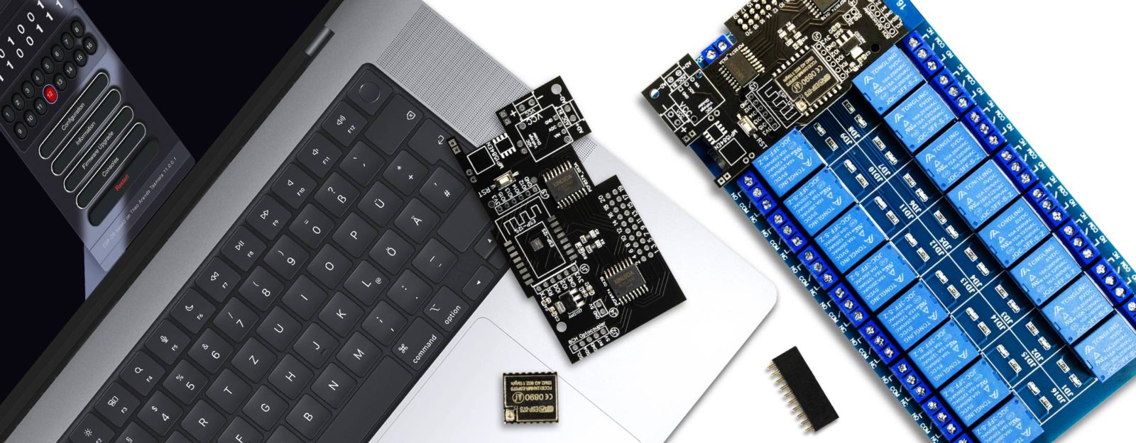
Die Hauptplatine
des EI-OT 4 Kanal Standard Relais Modul Bausatz verfügt bereits über grundlegende SMD Komponenten wie
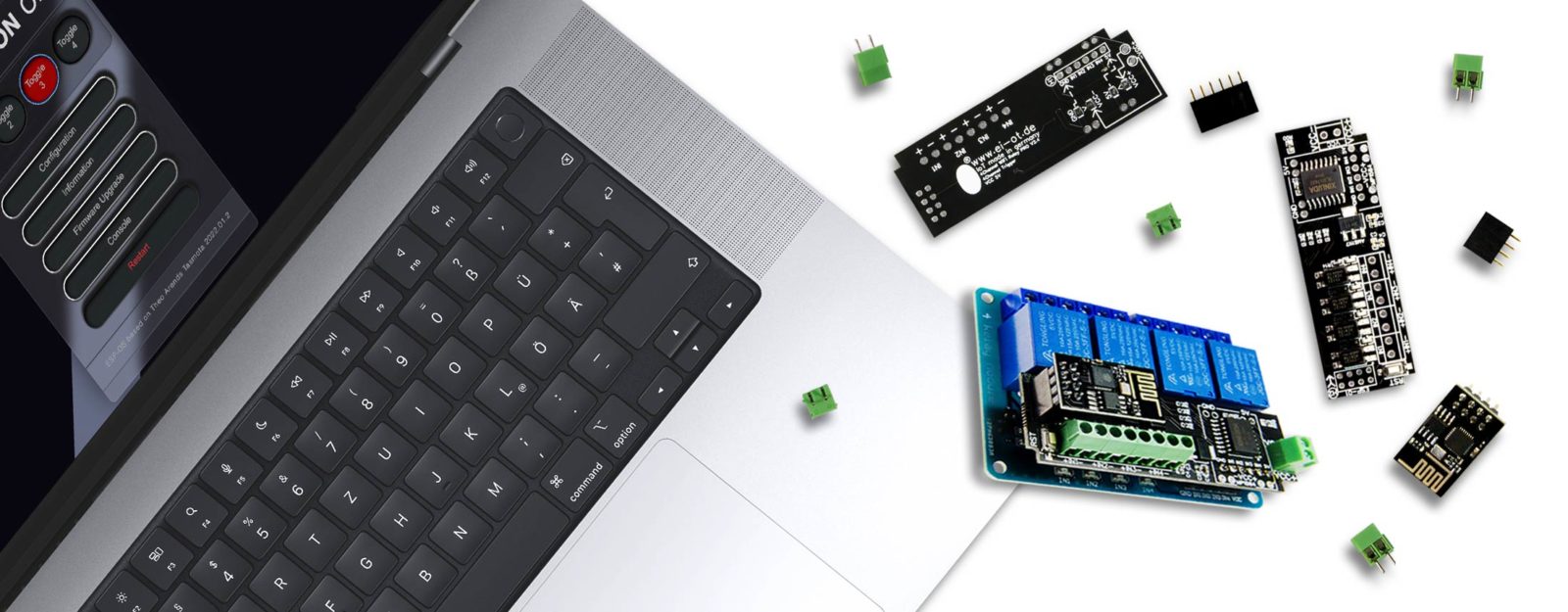
Bausatz Lieferumfang
Neben der Hauptplatine sind im EI-OT 4 Kanal Standard Relais Modul Bausatz folgende Komponenten enthalten:
GPIO und weitere Anschlüsse
Auf der Hauptplatine des EI-OT 4 Kanal Standard Relais Modul Bausatz wurden zusätzlich folgende Anschlüsse
auf eine 5-polige Pinleiste ausgeführt. Neben der Bereitstellung der ESP8266 UART Schnittstelle beispielsweise zum Flashen, können auch etwaige Sensoren zum Beispiel 1-Wire betrieben und mit 3,3V Spannung versorgt werden.
Die GPIO’s des EI-OT ESP-07S 4 Kanal Standard Relais Modul ist in der ESP-OS Firmware bereits vorkonfiguriert. Sobald in der ESP-OS Modul Auswahl das 4 Kanal Relais selektiert wurde werden die 4 GPIO’s zum Schalten der Relais festgelegt.
Die ESP-OS Firmware des EI-OT ESP8266 4 Kanal Relais hat Treiber für folgende Sensoren und Module bereits integriert 1-Wire Sensoren und Module:
I2C Sensoren und Module:
|
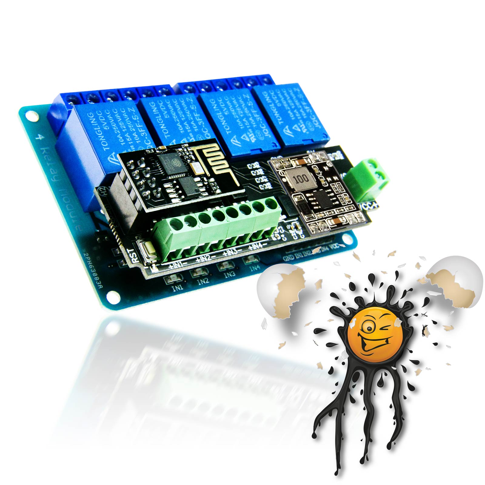
Our EI-OT ESP8266 4 Channel Standard Relais Module is perfect as WiFi based Smart Home control center for switching up to 4 devices. The EI-OT ESP-07S 4 Channel Standard Relais Module is based on AI Thinker ESP8266 ESP-07S Module to connect an external Antenna thru I-PEX connector. The ESP-07S 4Channel Standard Relay Module is optimized for stable connection over long distance. In combination with an external Antenna the ESP8266 has a better WiFi signal strength. The ESP8266 ESP-07S Modules have 32Mbit Flash ROM, flashed with ESP-OS Firmware for easy Smart Home Integration / Setup. The 4 Relays are switched thru
in combination with N-Channel Transistors. Therefore, during power supply of the 4 Channel Standard Relays Modul, while ESP8266 is booting, all 4 Relais are active (around 1 second). The EI-OT ESP-07S 4 Channel Standard Relais Module Board fits perfect for standard 5V Relay Modules and its connected thru 6-pole female socket. The EI-OT ESP8266 4 Channel Standard Relais Module requires only one central 5V Power Supply, KF350 2-pole Screw Connector.
The PCB
of the EI-OT ESP8266 4 Channel Standard Relais Module Kit comes assembled with basic SMD components such as
Scope of delivery Kit
besides the basic PCB the EI-OT ESP8266 4 Channel Standard Relais Module Kit includes:
GPIO additionally Connections
On a 5-pole Pinheader the EI-OT 4 Channel Standard Relays Module Board features
Besides the standard ESP8266 UART the GPIO can be used for external Devices such as Sensors or Expander.
The ESP-OS Firmware of the EI-OT 4 Channel Standard Relays Module its already preconfigured. Soon as the ESP-OS Firmware is configured as EI-OT 4CH Relay, the 4 GPIO’s are configured for toggling the 4 Relays.
The ESP-OS Firmware of the EI-OT 4 Channel Standard Relays Module comes with drivers for Sensors and Modules follows 1-Wire Sensors and Modules:
I2C Sensors und Modules:
|
s
FAQ Häufig gestellte Fragen
|
|


EI-OT ESP8266 ESP-07S 4 Channel Standard Relays Module Features
| VCC Spannungsversorgung | DC 5 WICHTIG | VCC / Input Voltage | DC 5 IMPORTANT |
|---|---|---|---|
| GPIO0 (frei wählbar) GPIO1 (frei wählbar) GPIO3 (frei wählbar) GPIO4 (Relais 3) GPIO5 (Relais 4) GPIO12 (Relais 2 ) GPIO13 (Relais 1) |
GPIO0 (User selection) GPIO1 (User selection) GPIO3 (User selection) GPIO4 (Relays 3) GPIO5 (Relays 4) GPIO12 (Relays 2 ) GPIO13 (Relays 1) |
||
|
250mA (max.) 23mA (Modem Sleep) 5mA (Light Sleep) <3mA (Deep Sleep) |
250mA (max.) 23mA (Modem Sleep) 5mA (Light Sleep) <3mA (Deep Sleep) |
||
|
|
||
| DS18B20, DHT11, AM2301, DHT22 | |||
| PCF8574,INA219, INA226, BH1750, TSL2561, SHT30, HTU-21, BMP085, BMP180, BMP280, BME280, BME680, SGP30, VL53L0X ToF, LM75AD, GY-521 / MPU-6050, AHT10, AHT15, AHT20, DHT12, MCP9808 | PCF8574,INA219, INA226, BH1750, TSL2561, SHT30, HTU-21, BMP085, BMP180, BMP280, BME280, BME680, SGP30, VL53L0X ToF, LM75AD, GY-521 / MPU-6050, AHT10, AHT15, AHT20, DHT12, MCP9808 | ||