Beschreibung

PC817 Optokoppler / Optocoupler Modul 1-20Ch 3,9-24Vin |
||||
|
Sensoren
Sensors Zubehör
Accessoires EI-OT Module
EI-OT Modules Benutzereingabe
User Input |
Das PC817 Optokoppler Modul erlaubt Eingangsspannungen von 3,9 bis 24V und eignet sich zur Umsetzung von Spannungen. Das Optokopplermodul basiert auf dem PC817 Optokoppler in Kombination mit
Der Signalausgang Out 4 und Out 3 ist nicht mit einem Widerstand zur Strombegrenzung beschaltet, der Maximalstrom beträgt 50mA. Das PC817 Optokoppler Modul ist wie folgt verfügbar:
Funktionsprinzip
Ein typischer Einsatzzweck für das PC817 Optkoppler Modul ist die galvansiche Trennung von Signalspannungen. Dies erfolgt durch eine integrierte
Wird die LED über IN1 / + und IN2 / – mit einer Spannung von 3,9 bis 24 Volt beschaltet, leuchtet die im PC817 befindliche LED. Der integrierte Empfänger schliesst zwischen Pin 4 / OUT4 und Pin 3 / OUT3, der PC817 Ausgang wird leitend, durchgeschaltet.
Dementsprechend eignet sich der PC817 Optokoppler zur Umsetzung von einer höheren Signalspannungen auf einen ESP8266 GPIO.
individuelle Anpassung
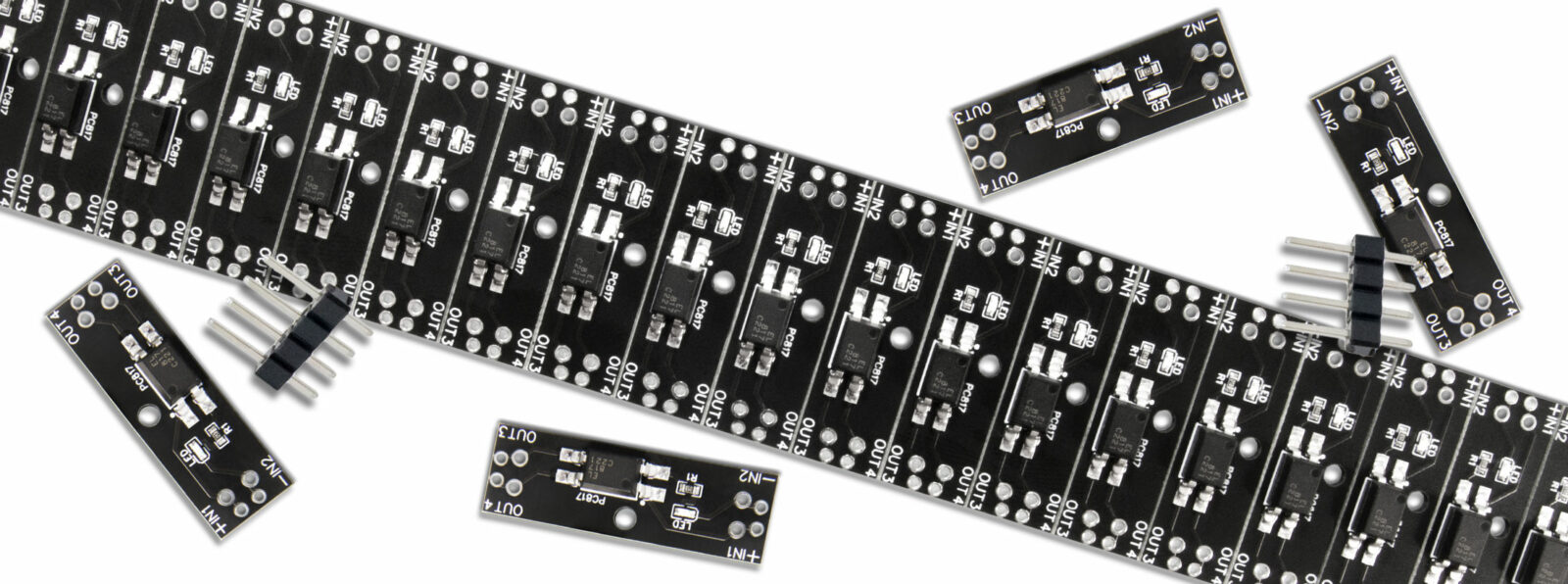
Die PC817 Optokoppler Modul Platine wird im V-Cut Verfahren hergestellt. Jedes PC817 Modul, jeder Kanal ist einzeln unterteilt und mittels Stamp Hole verbunden, sodass die Anzahl der Kanäle individuell angepasst werden kann. Die Lieferung erfolgt stets AM STÜCK, daß heißt es wird stets die Gesamtzahl der bestellten Module zusammenhängend, nicht getrennt geliefert. Dementsprechend kann dann, individuell je nach Anforderung die Anzahl der PC817 Kanäle durch brechen der Platine angepasst werden. Die maximale Anzahl an zusammenhängenden Modulen / Kanälen ist auf 20 Stück begrenzt.
Anwendungsbeispiel
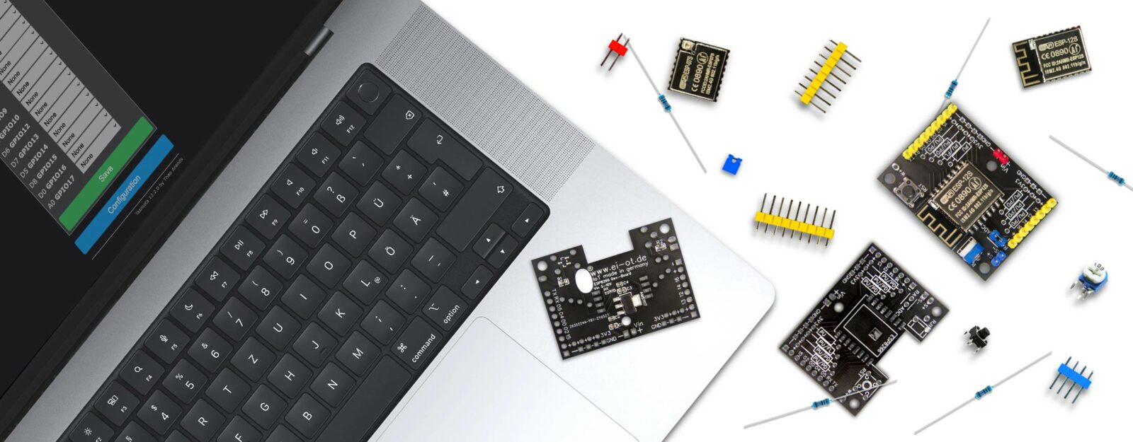
Typischerweise wird das PC817 Optokoppler Modul bei einem ESP8266 eingesetzt um eine Signalspannung auf die 3,3 Volt eines ESP8266 GPIO zu reduzieren. Hierzu muss lediglich die externe Signalspannung von 3,9 bis 24V auf +IN1 und -IN2 des PC817 Optokoppler Moduls gelegt werden. Der Ausgang Out4 des PC817 Optokoppler Moduls wird mit 3,3V, der Versorgungsspannung des ESP8266 belegt. OUT3 des PC817 Optokoppler Moduls wird auf einen ESP8266 GPIO gelegt. Hierbei bedarf es eines entsprechenden Pull-Down Widerstands, um den Grundzustand Low des jeweiligen GPIO’s wieder herzustellen. Sobald nun eine Signalspannung am Eingang des Optokoppler Moduls anliegt, werden die 3,3 Volt am Ausgang des Optokoppler Moduls auf den GPIO des ESP8266 geschaltet. Wird die Signalspannung vom PC817 Optokoppler getrennt, wird der GPIO des ESP8266 durch den Pull Down Widerstand auf LOW gezogen.
Das PC817 Optokoppler Modul ist neben dem ESP8266 selbstredend mit jedweder anderen MCU kombinierbar.
1-20 Kanal Optokoppler Modul für ESP8266 und weitere MCU’s
PC817 Optokoppler Modul:
|
The PC817 Optocoupler Module supports an Input Voltage from 3.9 to 24V. The Optocoupler Module is based on PC817 Optocoupler in combination with
The Output of the PC817 is without a current limiting resistor, maximal current is 50mA. The PC817 Optocoupler Module is available in 4 Versions
Working Principle
The PC817 is perfect to convert signal voltage to a higher or lower Voltage. The PC817 is galvanically isolated thru optoisolation based on
Soon as the PC817 is connected to power 3.9-24V (Pin1 / IN1+ and Pin2 / IN2-) the integrated LED lights up. The integrated optical receiver shorten contact between Pin4 / OUT4 and Pin3 / OUT3.
Therefore the PC817 is perfect to convert different voltage between ESP8266 GPIO and a higher voltage from external Input.
individual customization
The PC817 Module PCB is produced thru V-Cut process. Each PC817 Module / each Channel is separate Board connected thru breakable stamp hole. The PCB comes in one piece, based on amount of ordered PC817 Optocoupler Modules. Therefore the Board are customizable based on your requirements, amount of Channels. The maximum amount of Channels per Board is 20 PC817 Modules.
Application example
A typical Application for an Optocoupler Module in combination with an ESP8266 is external Voltage conversion to ESP8266 3.3V GPIO Level. The IN connection of the PC817 Module (+IN1 and -IN2) must be connected to external Signal Voltage (3.9V-24V). The OUT4 of the PC817 Optocoupler must be connected to ESP8266 3.3V Supply Voltage. OUT3 of the Optocoupler Module must be connected to a ESP8266 GPIO. There is a Pull-Down Resistor required to set basic GPIO LOW Level. Soon as external Signal Voltage is ON, Optocoupler OUT4 connects to OUT3 and the ESP8266 GPIO gets a HIGH Level. If the Signal is turend OFF, the Pull Down Resistor pulls the ESP8266 GPIO to LOW Level.
1 to 20 Channel Optocoupler Module for ESP8266 and other MCU’s
PC817 Optocoupler Module:
|
s
FAQ Häufig gestellte Fragen |
|