Beschreibung

ESP8266 Entwicklerplatine Development Kit 5-12V ADC Spannungsteiler Pull Widerstände |
||||
|
Spannungsversorgung
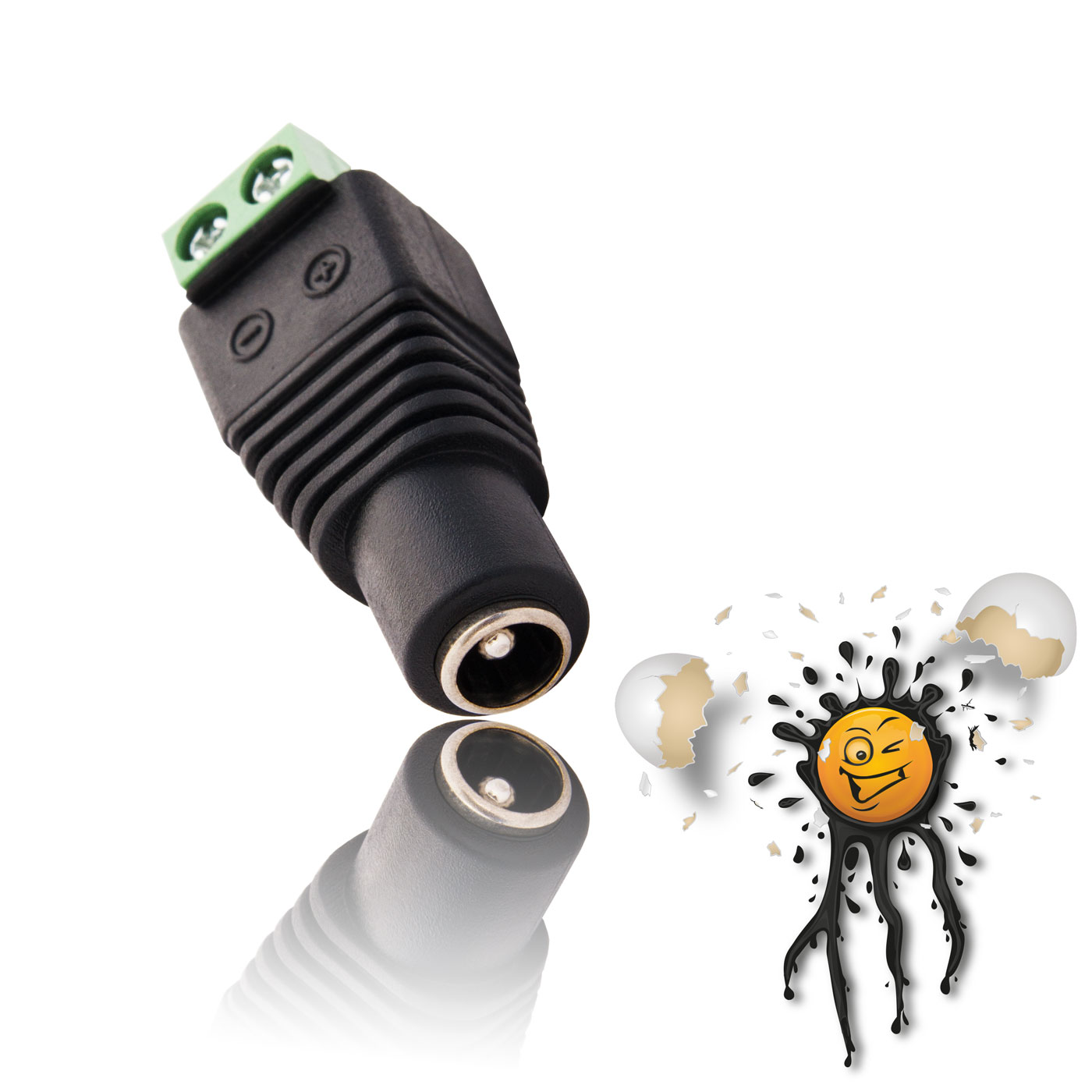
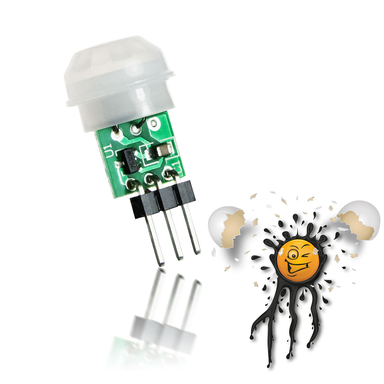
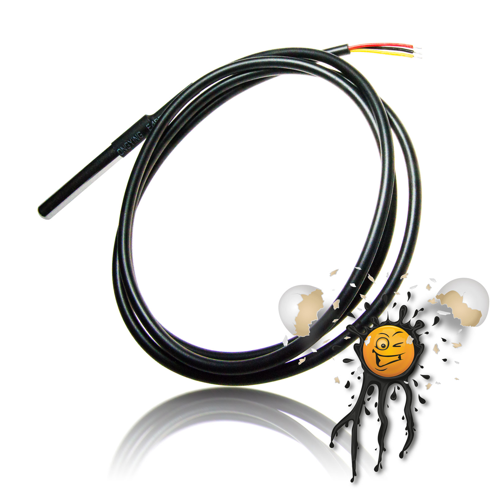
Power Supply Sensoren
Sensors
Erweiterungen
Extender Benutzereingabe
User Input Zubehör
Accessoires ESP8266
MCU EI-OT Module
EI-OT Modules |
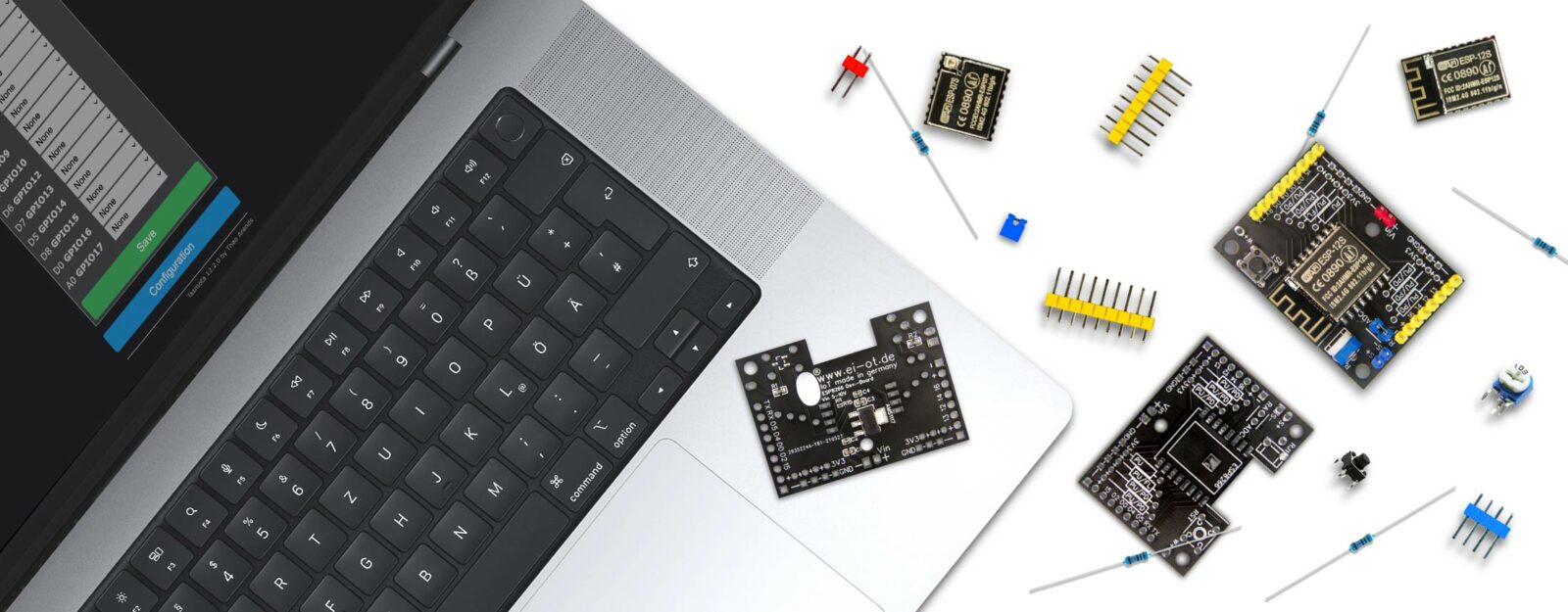
Die EI-OT ESP8266 Entwicklerplatine wurde für den Einsatz typischer ESP8266 Module wie
entwickelt. Funktionsprinzip
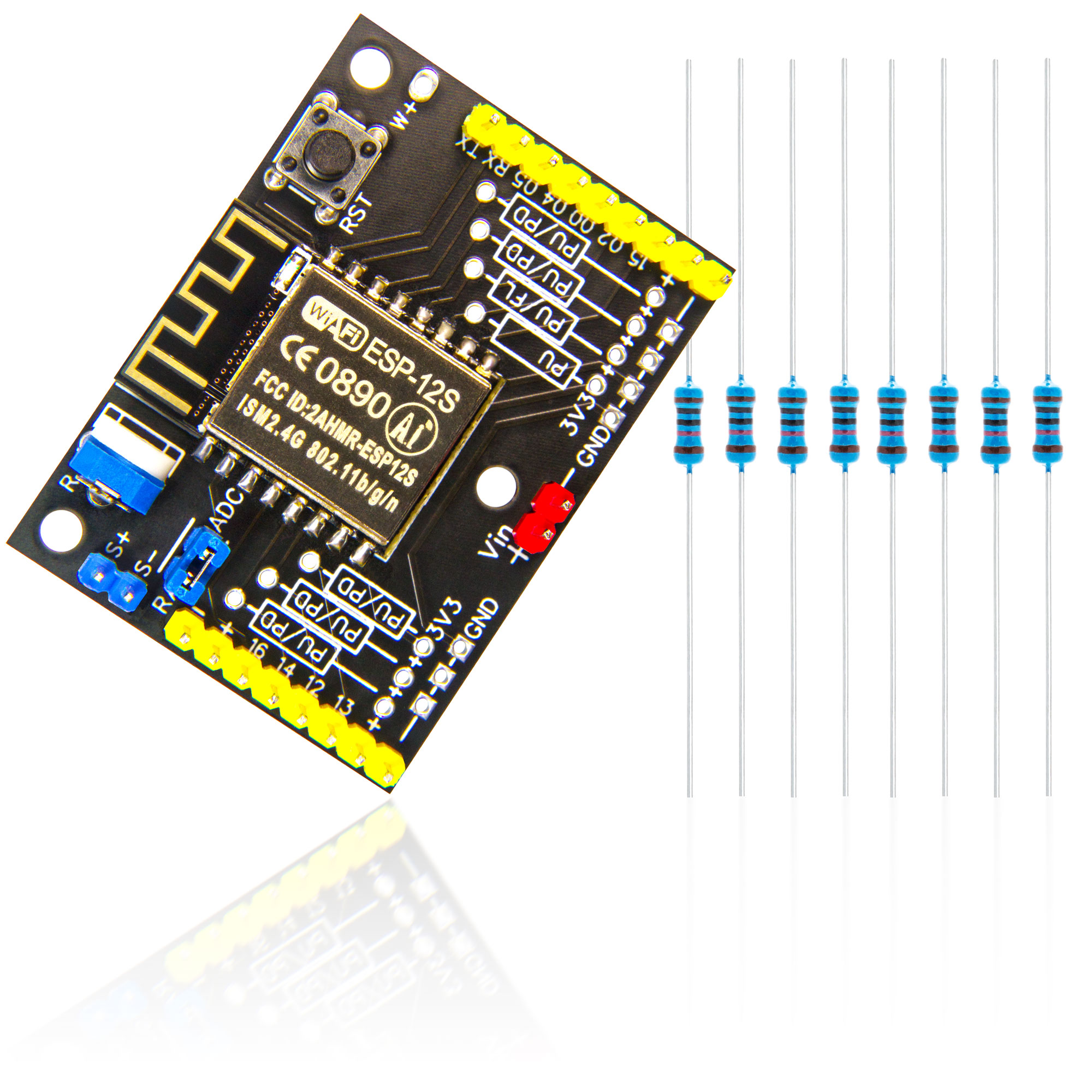
Im Vergleich zu typischen ESP8266 Entwicklerplatinen wurde die EI-OT ESP8266 Entwicklerplatine für einen weitreichenden praktischen Einsatz konzipiert. Bereits bei der Spannungsversorgung wird ein TLE42744GSV33 von Infineon verwendet. Diesbezüglich erlaubt das EI-OT ESP8266 Modul Spannungsversorgungen von 5-12V bei bis zu 400mA. Neben der typischen Ausführung der GPIO’s auf Stiftleisten (im Abstand von 2,54 mm angeordnet) stehen zusätzlich 3,3V Ausgänge zur Spannungsversorgung von beispielsweise Sensoren bereit.
analoger Signaleingang
Neben den digitalen GPIO’s verfügt die EI-OT ESP8266 Entwicklerplatine über einen analogen Signaleingang in Kombination mit einem variablen Spannungsteiler. Im Detail können analoge Eingangssignale mittels Potentiometer, individuell auf den ADC Eingang des ESP8266 eingestellt werden.
Pull Up & Pull Down Widerstände
Beim Einsatz der ESP8266 GPIO’s bedarf es typischerweise einem Pull Up oder Pull Down Widerstand. Die EI-OT ESP8266 Entwicklerplatine verfügt über entsprechende Kontakte um
um mit einem Widerstand zu beschalten.
Firmware
Der Funktionsumfang der EI-OT ESP8266 Entwicklerplatine wurde strikt den typischen und grundlegendem Funktionsprinzip des ESP8266EX angelehnt.
Die EI-OT ESP8266 Entwicklerplatine eignet sich somit für eigene Firmware Entwicklung als auch Firmware basierend auf
Die ESP8266 Entwicklerplatine
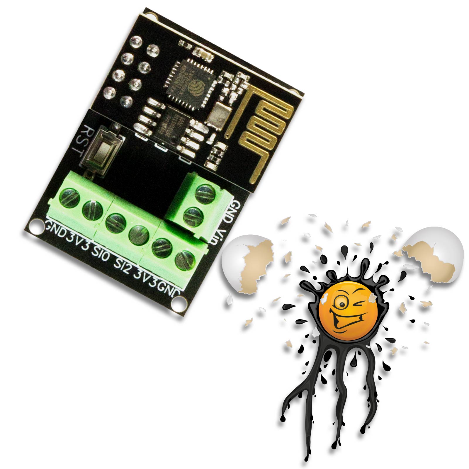
ist bereits auf der Rückseite mit grundlegende SMD Komponenten wie
bestückt.
EI-OT ESP8266 Entwicklerplatine Bausatz Lieferumfang
Neben der Hauptplatine sind im EI-OT ESP8266 Entwicklerplatinen Bausatz folgende Komponenten enthalten:
ESP8266 Entwicklerplatine für 5-12V VCC optimiert für den praktischen Einsatz
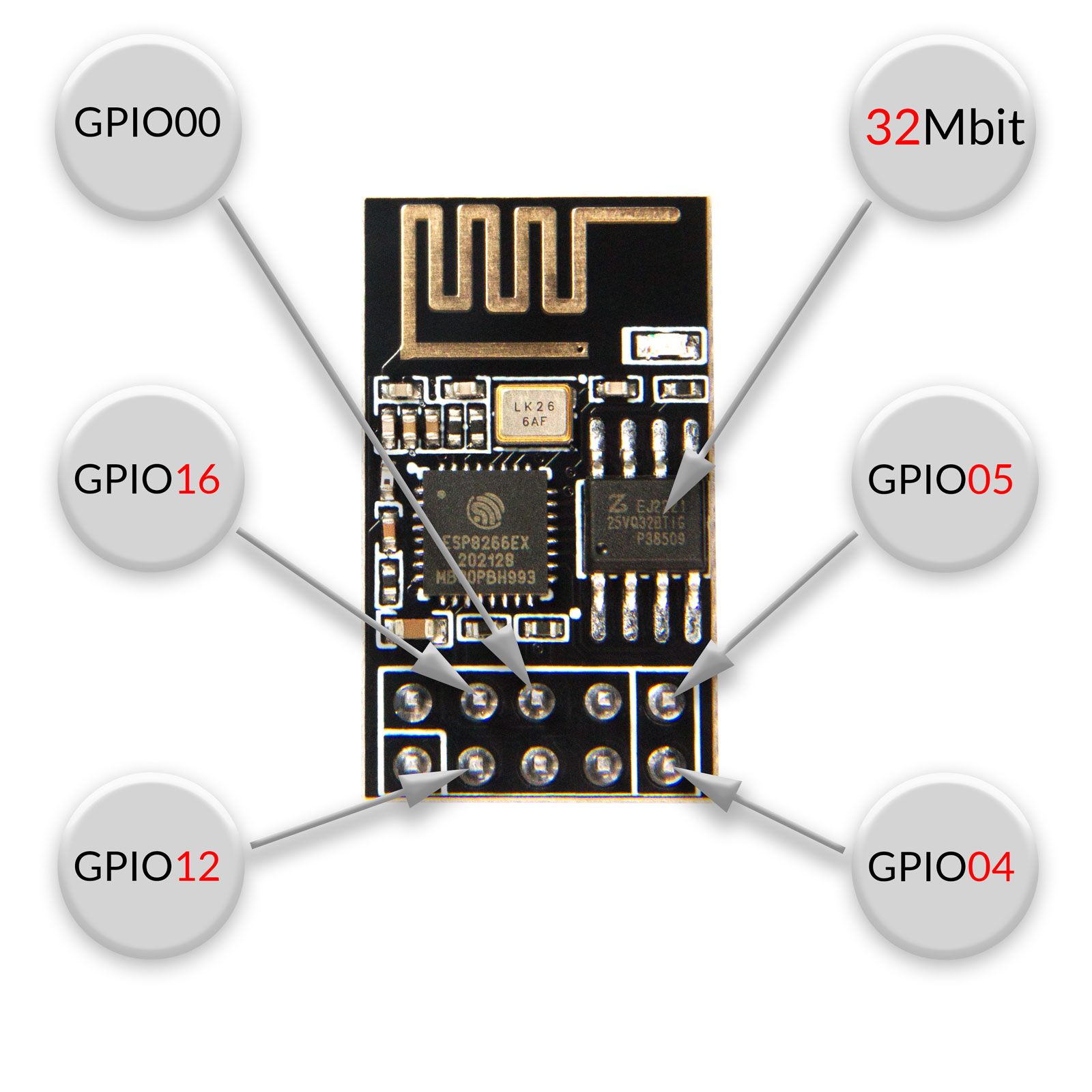
GPIO und weitere Anschlüsse
Bei der ESP8266 Entwicklerplatine wurde folgende Anschlüsse auf Pins (2,54mm raster) ausgeführt
|
The EI-OT ESP8266 developer board was designed for use with typical ESP8266 modules such as
Working Principle
Compared to typical ESP8266 developer boards, the EI-OT ESP8266 developer board is designed for wide-ranging practical use. A TLE42744GSV33 from Infineon is already used for the power supply. In this regard, the EI-OT ESP8266 module allows power supplies of 5-12V @ up to 400mA. In addition to the typical design of the GPIOs on pin strips (arranged at a distance of 2.54 mm), there are also 3.3V outputs available for the power supply of sensors, for example.
analog signal input
In addition to the digital GPIO’s, the EI-OT ESP8266 developer board has an analog signal input in combination with a variable voltage divider. In detail, analog input signals can be adjusted individually to the ADC input of the ESP8266 using a potentiometer.
Pull Up & Pull Down Resistors
When using the ESP8266 GPIO’s, a pull up or pull down resistor is typically required. The EI-OT ESP8266 developer board has corresponding contacts around
to connect GPIO with a resistor
Firmware
The range of functions of the EI-OT ESP8266 developer board was strictly based on the typical and basic functional principle of the ESP8266EX.
The EI-OT ESP8266 developer board is therefore suitable for your own firmware development as well as firmware based on
The ESP8266 Development Board
is already assembled with SMD components
The EI-OT ESP8266 Development Board Kit scope of delivery
In addition to the main board, the following components are included in the EI-OT ESP8266 developer board kit :
ESP8266 developer board for 5-12V VCC optimized for practical use
GPIO and additionally Connections
The ESP8266 developer board has the following connections on pins (2.54mm pitch).
|
s
FAQ Häufig gestellte Fragen
|
|


EI-OT ESP8266 Development Board Features
| VCC Spannungsversorgung | DC 5-12 Volt | VCC / Input Voltage | DC 5-12 Volt |
|---|---|---|---|
| je nach GPIO Konfiguration | based on GPIO configuration | ||
|
200mA (max.) 23mA (Modem Sleep) 5mA (Light Sleep) <3mA (Deep Sleep) |
200mA (max.) 23mA (Modem Sleep) 5mA (Light Sleep) <3mA (Deep Sleep) |
||
| – GND + 3,3V GPIO16 GPIO14 GPIO12 GPIO13 + 3,3V – GND |
– GND + 3.3V GPIO16 GPIO14 GPIO12 GPIO13 + 3.3V – GND |
||
| TX RX GPIO05 GPIO04 GPIO00 GPIO02 GPIO15 + 3,3V – GND |
TX RX GPIO05 GPIO04 GPIO00 GPIO02 GPIO15 + 3.3V – GND |
||
| S+ analoger Signaleingang S- GND analoger Signaleingang |
S+ analog signal input S- GND analog signal input |
||
| RA + variabler Signaleingang Spannungsteiler ADC analoger Signaleingang ESP8266 |
RA + adjustable signal input voltage divider ADC analog signal input ESP8266 |
||