EI-OT 5-12V ESP8266 Entwicklerplatine Bausatz
ESP8266 Entwickler Board

EI-OT ESP8266 ESP-12S ESP-07 Entwicklerplatine Zusammenbau

EI-OT ESP8266 Development Board ESP-12S ESP-07S Module assembling
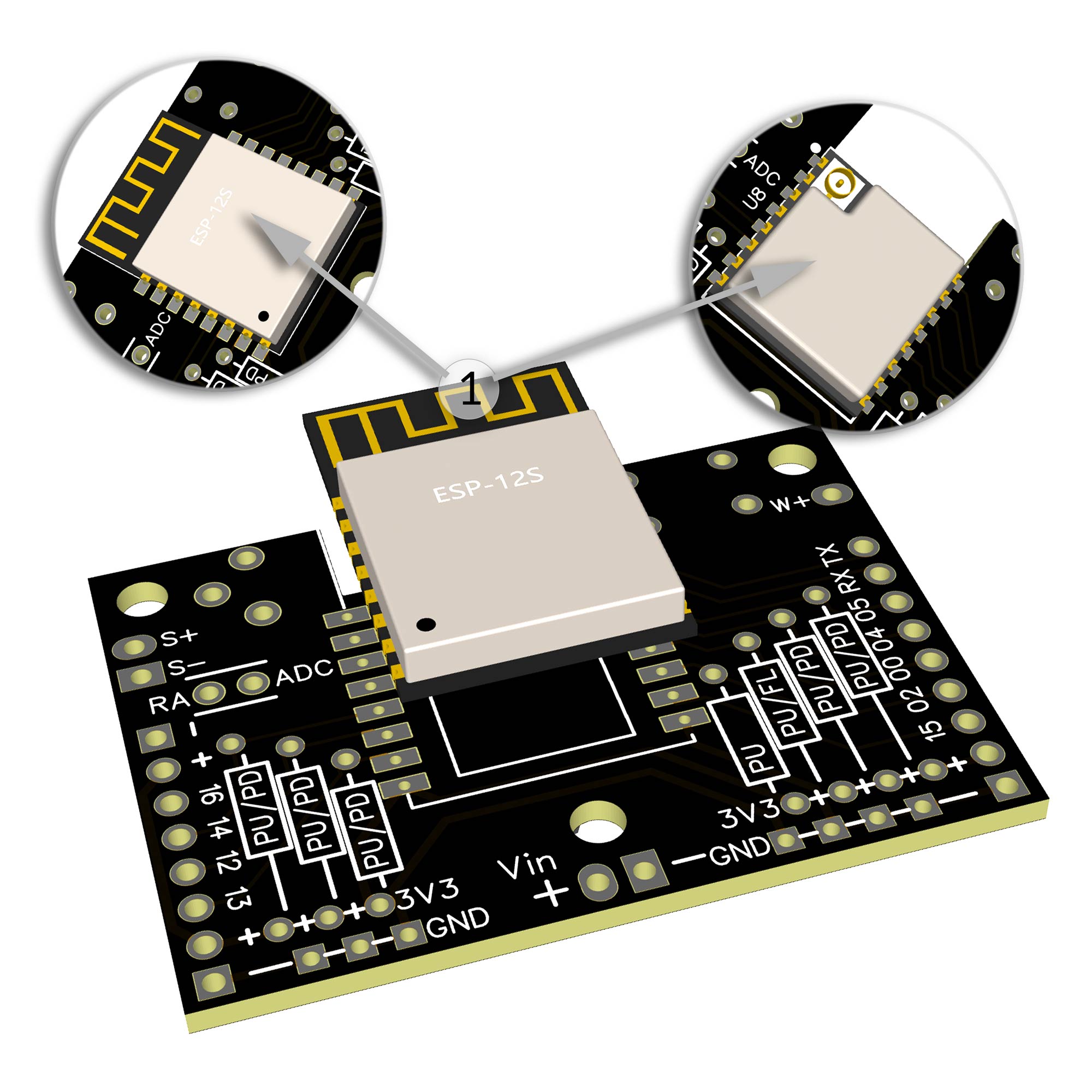
ESP8266 bestücken

Die EI-OT ESP8266 Entwicklerplatine ist bereits mit SMD Komponenten auf der Rückseite bestückt. Zur Inbetriebnahme müssen nachfolgende Komponenten wie in nebenstehender Grafik (zum Vergrößern auf das Bild klicken) bestückt / verlötet werden

Die Bestückung der EI-OT ESP8266 Entwicklerplatine Schritt für Schritt:

  1. Das ESP8266 Modul entsprechend platzieren, am besten mit einem Clip, z.B. Wäscheklammer fixieren und verlöten
ESP8266 Assembling

Besides the SMD components on bottom side of PCB, the EI-OT ESP8266 Development Break Out Module requires additional components.

Assembling of the 16 Channel PRO Relays Module Step by Step:

  1. Put the ESP8266 Module in correct direction on position, fix it with a clip or clothes peg and solder it.
  2. Put the 6-pole Pinheader on J1 and solder the Pins from backside
  3. Put the 2-pole Pinheader on A2 A1 and solder the Pins from backside

The basic assembling of the EI-OT 16 Channel PRO Relays Module is finished.

EI-OT ESP8266 Dev.-Kit ADC Potentiometer RST Button assembling
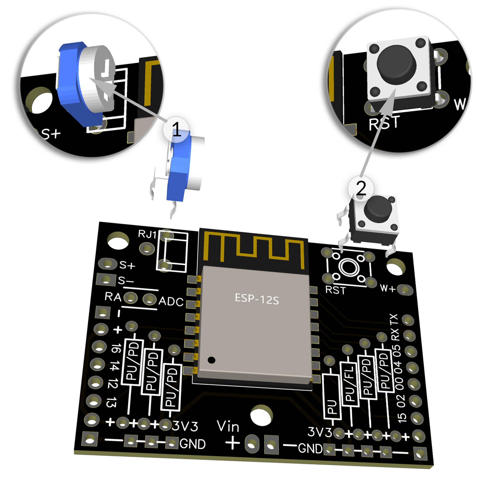
Poti Taster bestücken

Nachdem das ESP8266 LED Controller Modul mit dem ESP8266 bestückt wurde müssen der Potentiometer und der Reset Taster wie folgt bestückt werden:

  1. Platziere das RM063 Potentiometer auf RJ1 und verlöte die Pins auf der Rückseite
  2. Platziere den 6×6 Taster auf RST und verlöte die Pins auf der Rückseite
Poti Button Assembling

After assembling ESP8266 module on EI-OT ESP8266 Break Out Board, Reset Button and ADC Potentiometer must be assembled:

  1. Put the RM063 Potentiometer on RJ1 and solder the Pins from backside
  2. Put the 6×6 Button RST and solder the Pins from backside
EI-OT ESP8266 LED Stripe Controller TO220  assembling
Stiftleisten  bestücken

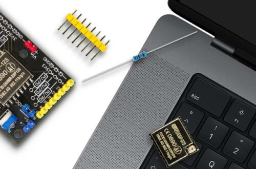
Zur besseren Differenzierung  umfasst der Lieferumfang des EI-OT ESP8266 Entwicklerkit farbige Pinleisten

  • gelb, seitliche Anschlüsse (GPIO’s und 3,3V Spannungsausgang)
  • rot, Spannungsversorgung (5-12V)
  • blau, ADC Anschluß sowie ADC Brücke / Jumper

BITTE VOR DEM BESTÜCKEN die entsprechende Farbe der Pinleiste berücksichtigen

  1. Platziere die 9-polige gelbe Pinleiste und verlöte die Pins auf der Rückseite
  2. Platziere die 2-polige rote Pinleiste und verlöte die Pins auf der Rückseite
  3. Platziere die 8-polige gelbe Pinleiste und verlöte die Pins auf der Rückseite
  4. Platziere die 2-polige blaue Pinleiste und verlöte die Pins auf der Rückseite
  5. Platziere die 2-polige blaue Pinleiste und verlöte die Pins auf der Rückseite

Die EI-OT ESP8266 Entwicklerplatine ist nun betriebsbereit und kann angeschlossen werden.

Pinheader Assembling

For better differentiation, the scope of delivery of the EI-OT ESP8266 developer kit includes colored pin strips

  • yellow, side connections (GPIO’s and 3.3V voltage output)
  • red, power supply (5-12V)
  • blue, ADC connection and ADC bridge / jumper

PLEASE consider the corresponding color of the pin strip BEFORE ASSEMBLING

  1. Place the 9-pin yellow pin header and solder the Pins from backside
  2. Place the2-pin red pin header and solder the Pins from backside
  3. Place the 8-pin yellow pin header and solder the Pins from backside
  4. Place the 2-pin blue pin header and solder the Pins from backside
  5. Place the 2-pin blue pin header and solder the Pins from backside

The EI-OT ESP8266 developer board is now assembled and can be connected.

Schreibe einen Kommentar

Deine E-Mail-Adresse wird nicht veröffentlicht. Erforderliche Felder sind mit * markiert