EI-OT 5-12V ESP8266 Entwicklerplatine Bausatz
ESP8266 Entwickler Board

EI-OT ESP8266 Entwickler Development Board Pull Up Pull Down Widerstand

Pull Up Pull Down Widerstand

Als typische MCU (MikroController Unit) verfügt der ESP8266 über GPIO’s (General Purpose Input/Output). Mit einfachen Worten ein Pin / Kontakt der individuell und anwendungsspezifisch genutzt werden kann, beispielsweise als

  • digitaler Eingang, mit High +3,3V und Low Level GND
  • Schnittstelle, 1-Wire oder im Verbund als Anschluss einer Schnittstelle als MOSI, MISO, CS, CLK, ….

Neben den individuell nutzbaren GPIO’s verfügt der ESP8266 auch über folgende GPIO’s die für interne Funktionen benötigt werden beispielsweise

  • GPIO0
    Low/GND Flash Modus aktiv
    High/3,3V+ Boot Modus aktiv
  • GPIO15
    Low/GND bootet vom SPI Flash
    High/3,3V+ bootet von einer SD Speicherkarte

Je nach Verwendung und Funktion eines GPIO bedarf es in der Regel (fast ausnahmslos) eines

  • Pull Up Widerstand, der zwischen 3,3V+
  • Pull Down Widerstand, der zwischen GND

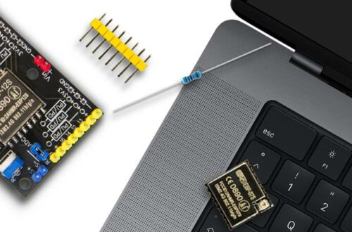
und dem jeweiligen GPIO geschaltet wird.

Die EI-OT ESP8266 Entwicklerplatine ist dementsprechend vorbereitet um bei Bedarf einen GPIO mit einem notwendigen Widerstand zu beschalten.

Pull Up Pull Down Widerstand

As a typical MCU (microcontroller unit), the ESP8266 has GPIOs (General Purpose Input/Output). In simple words, a pin / contact that can be used individually and application-specifically, for example as a

  • digital input, with high +3.3V and low level GND
  • Interface, 1-Wire or in combination as connection of an interface as MOSI, MISO, CS, CLK, ….

In addition to the individually usable GPIO’s, the ESP8266 also has the following GPIO’s that are required for internal functions, for example

  • GPIO0
    Low/GND flash mode active
    High/3.3V+ boot mode active
  • GPIO15
    Low/GND boots from the SPI Flash
    High/3.3V+ boots from an SD memory card

Depending on the use and function of a GPIO, usually a

  • Pull up resistor between 3.3V+
  • Pull down resistor between GND

and the respective GPIO is required.

The EI-OT ESP8266 developer board is prepared accordingly to connect a GPIO with a resistor if necessary.

ESP8266 Development Board Pull Up Pull Down Resistor connection
Pull Up anschliessen

Bitte stets auf entsprechenden Abstand zwischen Platine und Widerstand achten um einen Kurzschluss zu vermeiden

  1. platziere  einen Kontakt des bedrahteten Widerstand im jeweiligen GPIO Anschluss der EI-OT ESP8266 Entwicklerplatine und verlöte den Kontakt
  2. platziere den zweiten Kontakt des bedrahteten Widerstand an einem + 3V3 Anschluss der EI-OT ESP8266 Entwicklerplatine und verlöte den Kontakt
Pull Down anschliessen

Bitte stets auf entsprechenden Abstand zwischen Platine und Widerstand achten um einen Kurzschluss zu vermeiden

  1. platziere  einen Kontakt des bedrahteten Widerstand im jeweiligen GPIO Anschluss der EI-OT ESP8266 Entwicklerplatine und verlöte den Kontakt
  2. platziere den zweiten Kontakt des bedrahteten Widerstand an einem – GND Anschluss der EI-OT ESP8266 Entwicklerplatine und verlöte den Kontakt
Pull Up connection

Bitte stets auf entsprechenden Abstand zwischen Platine und Widerstand achten um einen Kurzschluss zu vermeiden

  1. place a contact of the wired resistor in the respective GPIO connection of the EI-OT ESP8266 developer board and solder the contact
  2. place the second contact of the wired resistor to a + 3V3 terminal of the EI-OT ESP8266 developer board and solder the contactConnection of the LDR is complete.
Pull Down connection

  1. place a contact of the wired resistor in the respective GPIO connection of the EI-OT ESP8266 developer board and solder the contact
  2. place the second contact of the wired resistor to a – GND terminal of the EI-OT ESP8266 developer board and solder the contact

Schreibe einen Kommentar

Deine E-Mail-Adresse wird nicht veröffentlicht. Erforderliche Felder sind mit * markiert