|
ESP8266 ADC Eingang
Der ESP8266 verfügt am GPIO17 über einen analogen Signaleingang. Mittels einem ADC (Analog Digital Converter) werden analoge Spannungswerter auf einen digitalen Wert von 0 bis 1023 umgesetzt. Der ESP8266 unterstützt dabei maximal 1000mV am ADC Signaleingang. Signalwerte über 1V können zu Beschädigung des ESP8266 führen. Diesbezüglich verfügt die EI-OT ESP8266 Entwicklerplatine über einen variablen, mittels Potentiometer einstellbaren Spannungsteiler, um den maximalen Signalwert individuell zu begrenzen. Die Verwendung, Anschluss und Einstellung wird nachfolgend am Beispiel eines einfachen LDR (lichtempfindlichen Widerstand) beschrieben. Selbstredend bedarf es einem Multimeter zur Messung von Gleichspannung um die Signalspannung entsprechend zu limitieren! |
ESP8266 ADC Input
The ESP8266 has an analog signal input on GPIO17. The GPIO17 has an ADC (Analog Digital Converter), to convert analog voltage values to a digital values from 0 to 1023. The ESP8266 supports a maximum of 1000mV at the ADC signal input. Signal values above 1V can damage the ESP8266. In this regard, the EI-OT ESP8266 developer board has a variable voltage divider that can be set using a potentiometer in order to individually limit the maximum signal value. Typical application, connection and setup is described below, using a simple LDR (Light Dependent Resistor) as an example. Of course you need a multimeter to measure DC voltage in order to limit the signal voltage accordingly. |
ESP8266 RGBW Module RGB LED and Power Supply connection 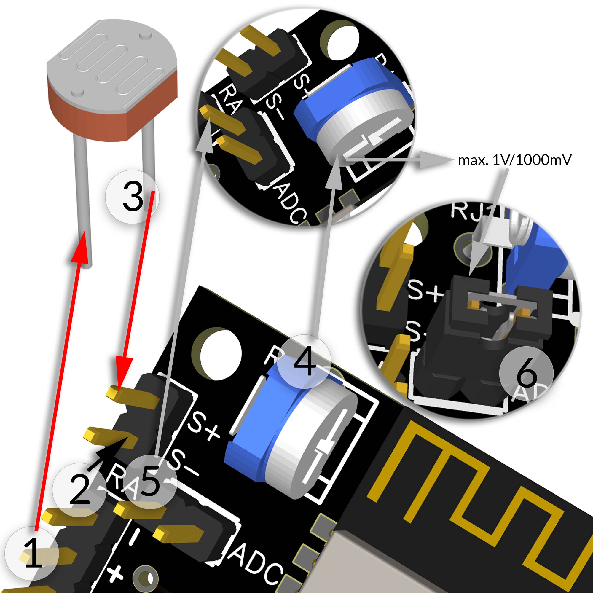 |
LDR anschliessen
Vor Beginn stelle sicher dass
Das Funktionsprinzip eines LDR ist sehr einfach, je stärker der Lichteinfall desto niedriger der Widerstand und somit die Ausgangsspannung. Dementsprechend wird der LDR über die EI-OT ESP8266 Entwicklerplatine mit 3,3V+ versorgt.
Der Anschluss des LDR ist abgeschlossen. Signalspannung einstellen
Vor Beginn stelle sicher dass
Versorge die EI-OT ESP8266 Entwicklerplatine mit Spannung. Die Ausgangsspannung des Spannungsteiler (Signalspannung) liegt nun am Pin RA (Resistor Adjust) an. 4. Mittels dem Potentiometer kann nun die Signalspannung (Pin RA) entsprechend variiert werden 5. Um die aktuelle Signalspannung zu messen muß lediglich die positive Prüfspitze des Multimeters mit Pin RA und die negative Prüfspitze mit GND verbunden werden 6. Sobald die Signalspannung / Ausgangsspannung des Spannungsteilers eingestellt (auf max. 1000mV limitiert) wurde, muss der Jumper auf RA und ADC gesetzt werden, sodass der ADC des ESP8266 ein digitales Signal ausgibt. |
LDR connection
Before you start, make sure
A LDR is a passive component that decreases resistance with respect to receiving luminosity (light) and increases signal voltage. Accordingly, the LDR is supplied with 3.3V+ via the EI-OT ESP8266 Development Board.
Connection of the LDR is complete. Signal voltage adjustment
Before you start, make sure
Supply the EI-OT ESP8266 Development Board with voltage. The output voltage of the voltage divider (Signal Voltage) is now present at Pin RA. 4. The signal voltage (Pin RA) can now be varied thru the potentiometer 5. To measure the current signal voltage, you only have to connect the positive test tip of the multimeter to Pin RA and the negative test tip to GND 6. Once the signal voltage / output voltage of the voltage divider has been set / limited to max. 1000mV, the jumper must be placed on RA and ADC to forward signal voltage to ESP8266 ADC. |