ESP-01+ ESP8266 Deep Sleep Entwicklerplatine Bausatz Konfiguration
ESP-01+ ESP8266 Deep Sleep Board

EI-OT ESP-01+ ESP8266 Entwicklerplatine Zusammenbau

EI-OT ESP-01+ ESP8266 Deep Sleep Development Board assembling
ESP-01+ Platine bestücken

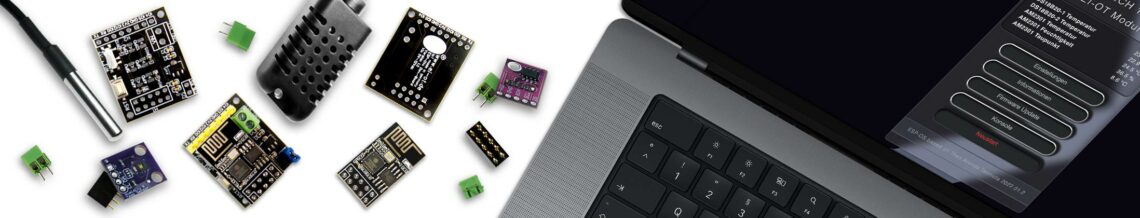
Die EI-OT ESP-01+ Entwicklerplatine ist bereits mit SMD Komponenten wie

  • AMS1117 3,3V Spannungskonverter nebst Kondensatoren
  • Reset Taster
  • Deep Sleep Wake-Up Schiebeschalter
  • Pull Up / Pull Down Widerständen

bestückt.

Zur Inbetriebnahme müssen nachfolgende Komponenten wie in nebenstehender Grafik (zum Vergrößern auf das Bild klicken) bestückt / verlötet werden

Die Bestückung des EI-OT ESP-01+ ESP8266 Entwicklerboard Schritt für Schritt:

  1. Platziere die KF350 Schraubklemme auf VIN und verlöte die Pins auf der Rückseite
  2. Platziere den 2×5 Pin Stecksockel auf H1 und verlöte die Pins auf der Rückseite
  3. Platziere die 8-polige Pinleiste auf H2 und verlöte die Pins auf der Rückseite
  4. Platziere die 2-polige Pinleiste auf DS und verlöte die Pins auf der Rückseite

Das EI-OT ESP-01+ ESP8266 Entwickler Board ist fertig bestückt.

ESP-01+ Board assembling

Besides the assembled SMD components

  • AMS1117 3.3V Voltage Converter and capacitors
  •  Reset Button
  • Deep Sleep Wake-Up Switch

requires additional components.

Assembling of the EI-OT ESP-01+ Development Board Step by Step:

  1. Put the KF350 screw terminal on VIN and solder the Pins from backside
  2. Put the 5×2 pole Pin Socket on H1 and solder the Pins from backside
  3. Put the 8-pole Pinheader on H2 and solder the Pins from backside
  4. Put the 2-pole Pinheader on DS and solder the Pins from backside

The basic assembling of the EI-OT ESP-01+ Development Board is finished.

Schreibe einen Kommentar

Deine E-Mail-Adresse wird nicht veröffentlicht. Erforderliche Felder sind mit * markiert