
|
Pull Up Pull Down Widerstand
Als typische MCU (MikroController Unit) verfügt der ESP-01+ über GPIO’s (General Purpose Input/Output). Mit einfachen Worten ein Pin / Kontakt der individuell und anwendungsspezifisch genutzt werden kann, beispielsweise als
Neben den individuell nutzbaren GPIO’s verfügt der ESP-01+ auch über folgende GPIO’s die für interne Funktionen benötigt werden beispielsweise
Je nach Verwendung und Funktion eines GPIO bedarf es in der Regel (fast ausnahmslos) eines
und dem jeweiligen GPIO geschaltet wird. Die EI-OT ESP-01+ Entwicklerplatine verfügt bereits über folgende Widerstände
|
Pull Up Pull Down Widerstand
As a typical MCU (microcontroller unit), the ESP-01+ has GPIOs (General Purpose Input/Output). In simple words, a pin / contact that can be used individually and application-specifically, for example as a
In addition to the individually usable GPIO’s, the ESP-01+ also has the following GPIO’s that are required for internal functions, for example
Depending on the use and function of a GPIO, usually a
and the respective GPIO is required. The EI-OT ESP-01+ developer board has
|
ESP-01+ Development Board Pull Up Pull Down Resistor connection 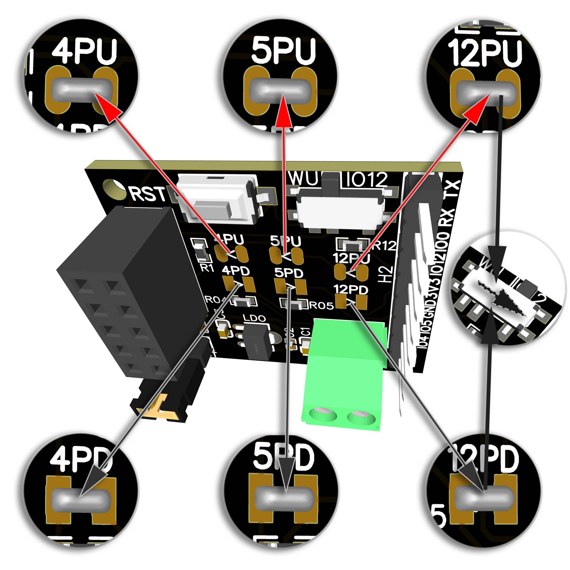 |
Pull Up aktivieren
Um einen Pull Up Widerstand für einen GPIO zu aktivieren müssen lediglich die jeweiligen Lötpads
verbunden (geschlossen) werden. Pull Down aktivieren
Um einen Pull Down Widerstand für einen GPIO zu aktivieren müssen lediglich die jeweiligen Lötpads
verbunden (geschlossen) werden. |
enable Pull Up
to enable Pull Up Resistor to a GPIO the solder pads
has to be connected. enable Pull Down
to enable Pull Down Resistor to a GPIO the solder pads
has to be connected. |