Beschreibung
PCF8574 I2C 8 Kanal PC817 Optokoppler Input Trigger Modul |
||||
|
related items Erweiterungen
|
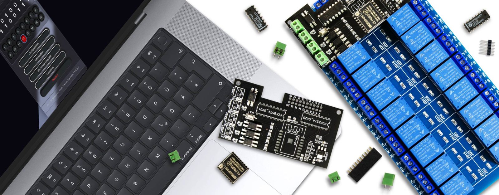
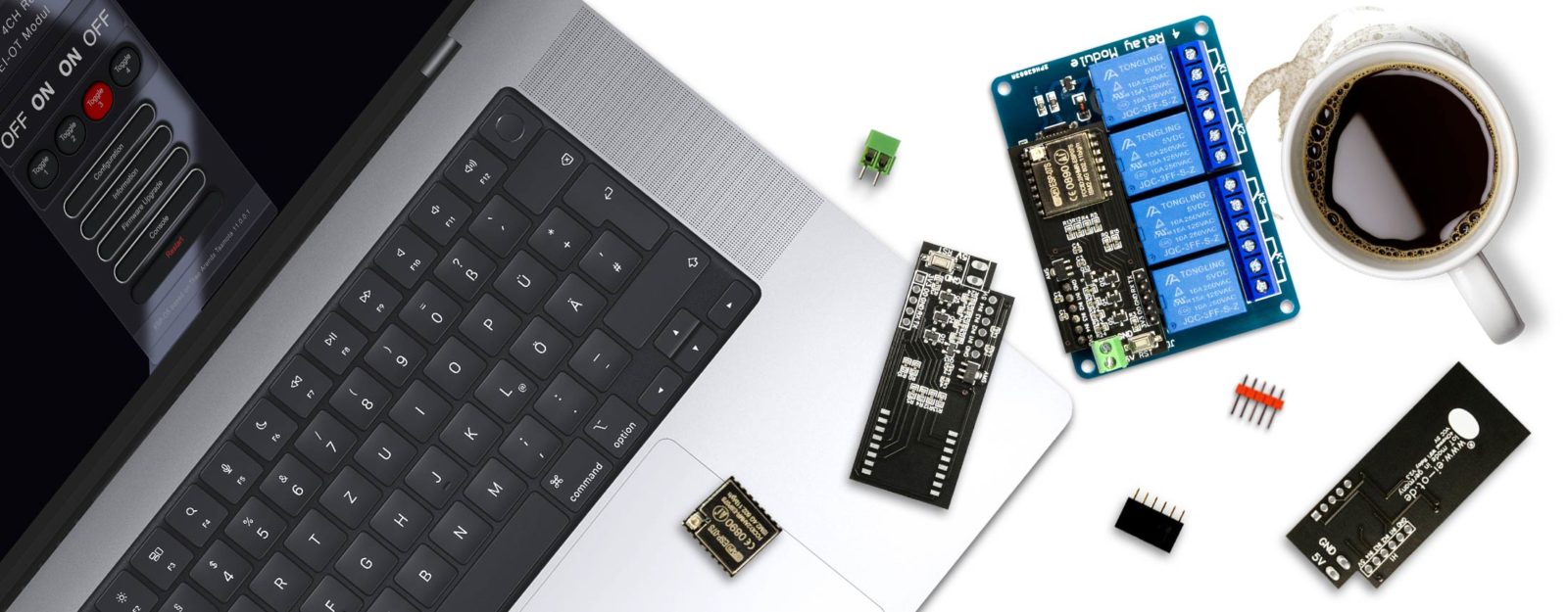
Das EI-OT PCF8574 I2C 8 Kanal PC817 Optokoppler Input Trigger Modul ist eine ideale Erweiterung für unsere EI-OT Relais Module wie das
Neben den kombinierten Einsatz mit unseren PRO Relais Modulen kann das PCF8574 I2C 8 Kanal PC817 Optokoppler Input Trigger Modul mit jedweder MCU über I2C betrieben werden. Das PCF8574 I2C 8 Kanal PC817 Optokoppler Input Trigger Modul basiert auf dem PCF8574A in Kombination mit 8 Stück PC817 Optokopplern. Jeder der 8 Eingangskanäle ist mittels einem PC817 Optokoppler galvansich getrennt und erlaubt Eingangsspannungen von 3,6V bis 24V. Das PCF8574 I2C 8 Kanal PC817 Optokoppler Input Trigger Modul eignet sich perfekt zur Erfassung von Benutzereingaben oder die Erfassung von HIGH / LOW Level beispielsweise von Sensoren. Die Signalumsetzung erfolgt über 8 invertierte Eingangskanäle (1=AUS / 0=AN) des PCF8574 und werden über I2C auf den ESP8266 bzw. anderweitige MCU’s über einen I2C Bus übertragen. Dementsprechend ist jeder Kanal des PCF8574 mit einem Pull Up Widerstand beschaltet, sodass die Grundkonfiguration Ausgang für jeden Kanal unterbunden wird. An dieser Stelle sei auf PCF8574 Dokumentationen verwiesen, wird ein PC8574 Kanal LOW beschaltet, wird der Kanal bei Spannungsversorgung als Ausgang konfiguriert. Dementsprechend sollten vorzugsweise die Eingangssignale, die Benutzereingabe über Taster (nicht Schalter) erfolgen.
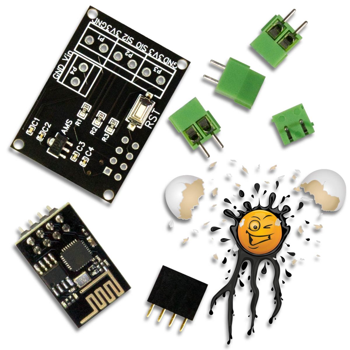
Die Hauptplatine
des EI-OT PCF8574 I2C 8 Kanal PC817 Optokoppler Input Trigger Modul Bausatz verfügt bereits über grundlegende SMD Komponenten wie
Bausatz Lieferumfang
Neben der Hauptplatine sind im EI-OT PCF8574 I2C 8 Kanal PC817 Optokoppler Input Trigger Modul Bausatz folgende Komponenten enthalten:
Der INT (Interrupt) Pin ist nicht beschaltet, zur Verwendung müssen die Pad’s R3 auf der Vorderseite der Platine geschlossen werden
PCF8574A I2C Adressen:
|
Our EI-OT PCF8574 I2C 8 Kanal PC817 Optocoupler Input Trigger Module is optimized for our PRO Relays Module
Also, the PCF8574 I2C 8 Kanal PC817 Optocoupler Input Trigger Module could be operated with every MCU thru I2C. The PCF8574 I2C 8 Kanal PC817 Optocoupler Input Trigger Module is based on a PCF8574A in combination with 8 pcs. PC817 Optocoupler. Each Input channel is galvanically isolated thru a PC817 Optocoupler and supports an Input Voltage from 3.6V up to 24V. The Input Signals of the PCF8574 I2C 8 Kanal PC817 Optocoupler Input Trigger Module are operated as 8 inverted Input channels (1=OFF 0=ON). The Signal Conversion is based on typical PCF8574 Libraries thru an I2C Bus. In simple words every PCF8574 Input Channel has a Pull Up Resistor, to prevent the PCF8574 set each channel with LOW level as output. Please refer PCF8574 documentation, if a PCF8574 channel has a LOW Level, PCF8574 indicates the channel as output. In this regard only Buttons are recommended for user Input.
The PCB
of the EI-OT PCF8574 I2C 8 Kanal PC817 Optocoupler Input Trigger Module Kit comes assembled with basic SMD components such as
Scope of delivery Kit
besides the basic EI-OT PCF8574 I2C 8 Kanal PC817 Optocoupler Input Trigger Module Kit includes:
The INT (Interrupt) Pin is not connected, for usage connect R3 Pad’s on top of PCB PCF8574A I2C Adresses
|
s
FAQ Häufig gestellte Fragen
|
|
EI-OT PCF8574 I2C 8 Kanal PC817 Optocoupler Input Trigger Module Features
| VCC Spannungsversorgung | DC 2,5V – 6V | VCC / Input Voltage | DC 2.5V – 6V |
|---|---|---|---|
| 8 invertiert (HIGH Level) | 8 inverted (HIGH Level) | ||
| < 200 mA | < 200 mA | ||