EI-OT INA226 ESP8266 Tasmota Modulbausatz 5-18V Bestückung und Konfiguration
Tasmota INA226 Strom- Current- Sensor Modul 5-18V

EI-OT Tasmota INA226 Stromsensor Modul 5-18V Zusammenbau

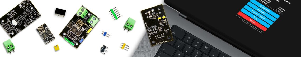
EI-OT ESP-01+ ESP8266 INA226 5-18V Board assembling
EI-OT 5-18V Stromsensor Modul bestücken

Das EI-OT INA226 5-18V Modul ist bereits mit SMD Komponenten wie

  • AMS1117 3,3V Spannungskonverter nebst Kondensatoren
  • Shunt Widerstand
  • INA226 Stromsensor
  • Widerständen

bestückt.

Zur Inbetriebnahme müssen lediglich, nachfolgende Komponenten wie in nebenstehender Grafik dargestellt bestückt / verlötet werden.

Die Bestückung des EI-OT INA226 5-18V Stromsensor Moduls Schritt für Schritt:

Bitte beachten als Unterseite wird im nachfolgenden die Platinenseite mit den SMD Komponenten bezeichnet!

  1. Platziere den 6×6 Microtaster auf RESET und verlöte die Pins auf der Unterseite
  2. Platziere den 2×5 Pin Stecksockel auf H1 und verlöte die Pins auf der Rückseite
  3. Platziere die 6-polige Pinleiste auf H2 und verlöte die Pins auf der Rückseite
  4. Platziere die 2-polige Pinleiste auf AJ und verlöte die Pins auf der Rückseite
  5. Platziere die 3-polige Pinleiste auf VJ und verlöte die Pins auf der Rückseite
  6. Platziere die KF129 Schraubklemme auf VIN und verlöte die Pins auf der Rückseite
  7. Platziere die KF129 Schraubklemme auf GND und verlöte die Pins auf der Rückseite

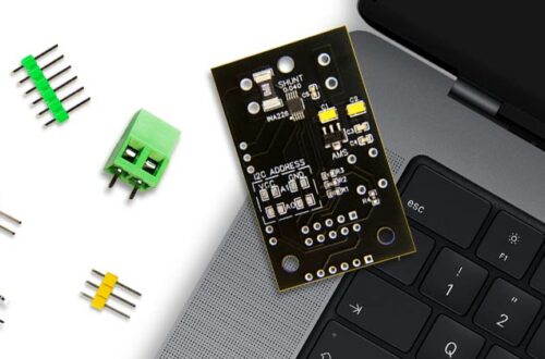
Das EI-OT INA226 5-18V Stromsensor Modul ist fertig bestückt.

EI-OT 5-18V Current Sensor Module assembling

The EI-OT INA226 5-18V module is already equipped with SMD components such as

  • AMS1117 3.3V Voltage Converter and capacitors
  • Shunt Resistor
  • INA226 Current Sensor IC
  • Resistors

For completion, the following components simply need to be assembled/soldered as shown in the graphic below.

The assembly of the EI-OT INA226 5-18V current sensor module step by step:

Please note that the bottom side is referred to below as the board side with the SMD components!

  1. Place the 6×6 micro button on RESET and solder the pins on the bottom side
  2. Place the 2×5 pin socket on H1 and solder the pins on the bottom side
  3. Place the 6-pin header on H2 and solder the pins on the bottom side
  4. Place the 2-pin  header on AJ and solder the pins on the bottom side
  5. Place the 3-pin  header on VJ and solder the pins on the bottom side
  6. Place the KF129 screw terminal on VIN and solder the pins on the bottom side
  7. Place the KF129 screw terminal on GND and solder the pins on the bottom side

The basic assembling of the EI-OT INA226 Current Sensor Module is finished.

Schreibe einen Kommentar

Deine E-Mail-Adresse wird nicht veröffentlicht. Erforderliche Felder sind mit * markiert