
EI-OT ESP8266 4 Kanal PRO Relais Modul Zusammenbau und Bestückung
Die Bestückung der Platine sowie Zusammenbau
- EI-OT 4 Kanal PRO Relais Modulbausatz bestücken
- EI-OT 4 Kanal PRO Relais Platine mit 4 Kanal Relais Modul verbinden
EI-OT 4 Channel PRO Relays Module assembling 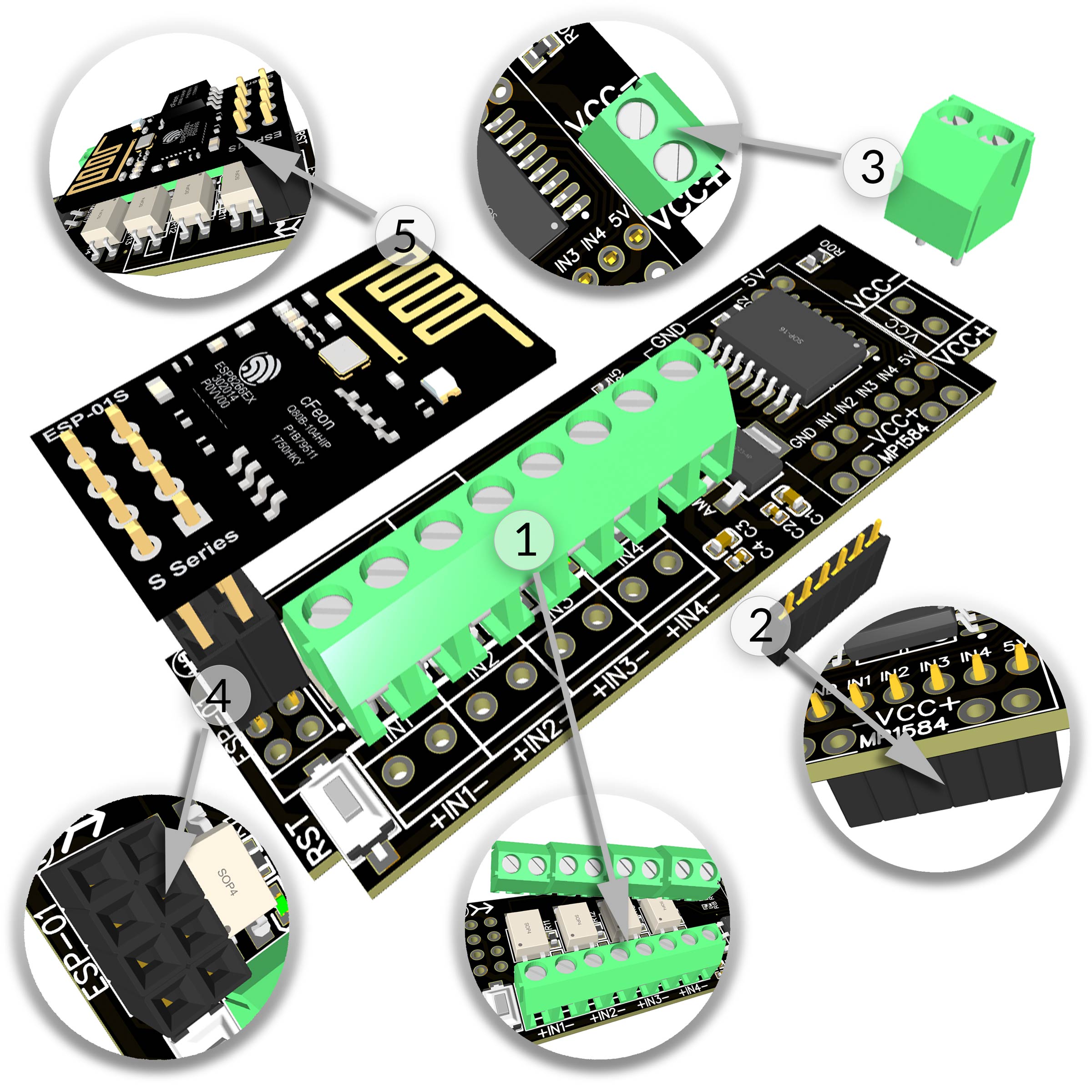 |
Zusammenbau / Bestückung
Das EI-OT ESP8266 4 Kanal PRO Relais Modul ist bereits mit SMD Komponenten bestückt. Zur Inbetriebnahme müssen nachfolgende Komponenten wie in nebenstehender Grafik (zum Vergrößern auf das Bild klicken) bestückt / verlötet werden
Die Bestückung des EI-OT 4 Kanal PRO Relais Modul Schritt für Schritt:
|
Assembling
Besides the SMD components, the EI-OT 4 Channel PRO Relays Module requires additional components.
Assembling of the 4 Channel PRO Relays Module Step by Step:
|
EI-OT PCB 4 Channel PRO Relays Module 5V Power Supply |
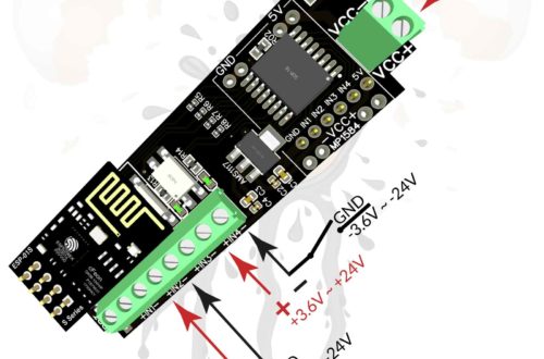
Relais Modul 5V Spannungsversorgung
Um EI-OT PRO Relais Module mit Spannungen von 7-26V betreiben zu können, kann die Platine zusätzlich mit einem MP1584 5V Spannungskonverter bestückt werden.
Wird das EI-OT 4 Kanal PRO Relais Modul mit 5V betrieben, so muss die Spannungsversorgung der Relais mittels einer Brücke hergestellt werden.
Auf der Unterseite befinden sich hierzu 4 Pads
|
Relays Module 5V Power Supply
In combination with a MP1584 5V Voltage Converter Module the EI-OT PRO Relais Module could be operated with 7-26V. If a MP1584 Module is assembled, the Output Voltage is directly connected to 5V Input of the EI-OT 4 Channel PRO relays Module.
In case of EI-OT 4 Chanel PRO Relays Module is operated with 5V power supply 4 pads on bottom side must be connected
|
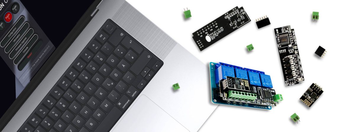
Assembling EI-OT PCB and Standard 4 Channel PRO Relays Module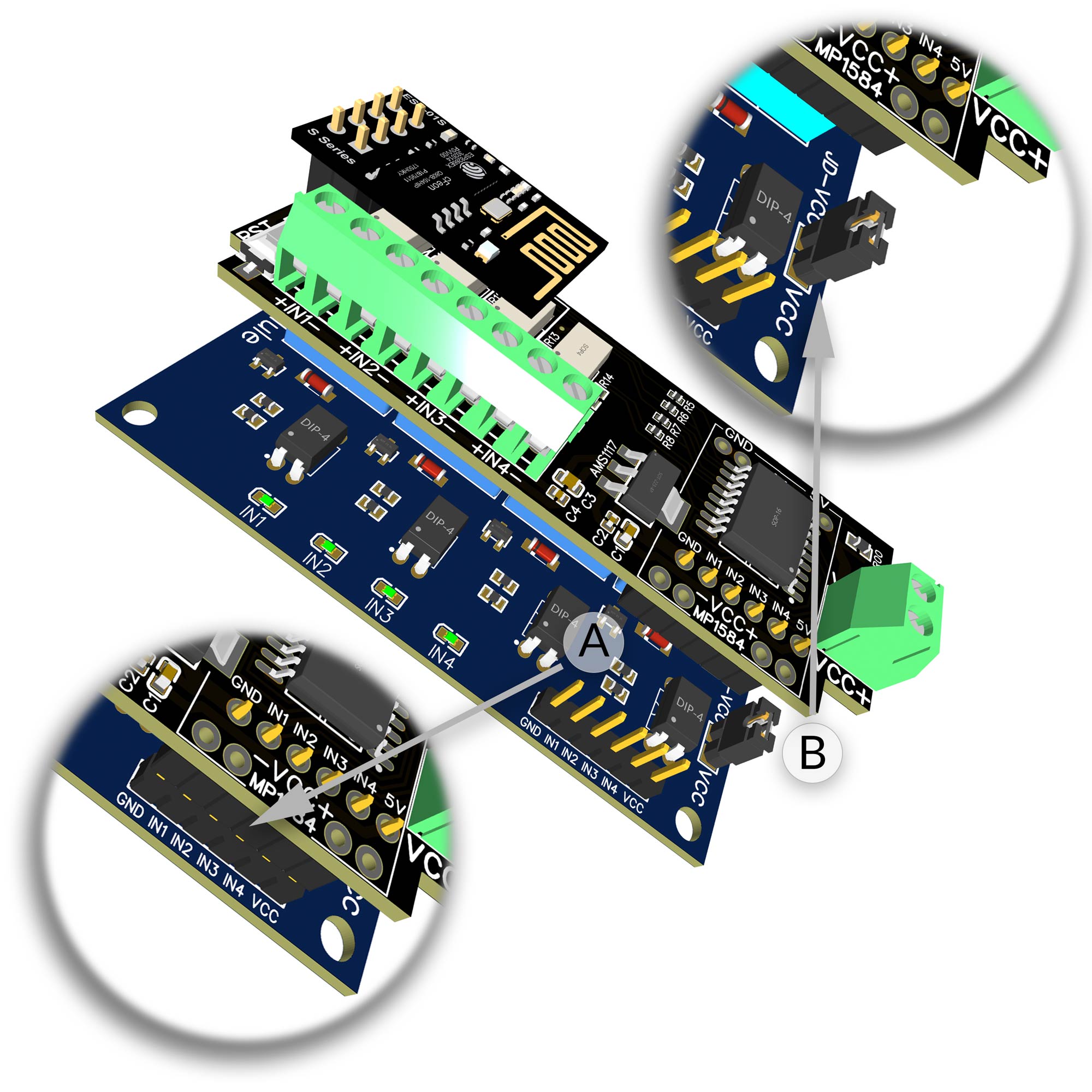 |
Relais Modul verbinden
Sobald die Platine fertig bestückt wurde, können Steuerungsplatine und das 4 Kanal PRO Relais Modul zusammengesetzt werden.
|
Relays Module Connection
Soon as the PCB is assembled, the controller PCB and the Relays Module can be assembled.
|