EI-OT ESP-07S Smart Home 4 Kanal RGBW LED Controller Bausatz

15,70 

Das Tasmot ESP-07S RGBW LED Controller Board zum Betrieb von
RGBW 4 Kanal, RGB 3 Kanal LED Streifen für LED im Spannungsbereich von 5V bis 24V

Beschreibung

Tasmota ESP-07S 4 Kanal RGBW LED Controller Modul Bausatz

Spannungsversorgung
Power Supply
Antennen
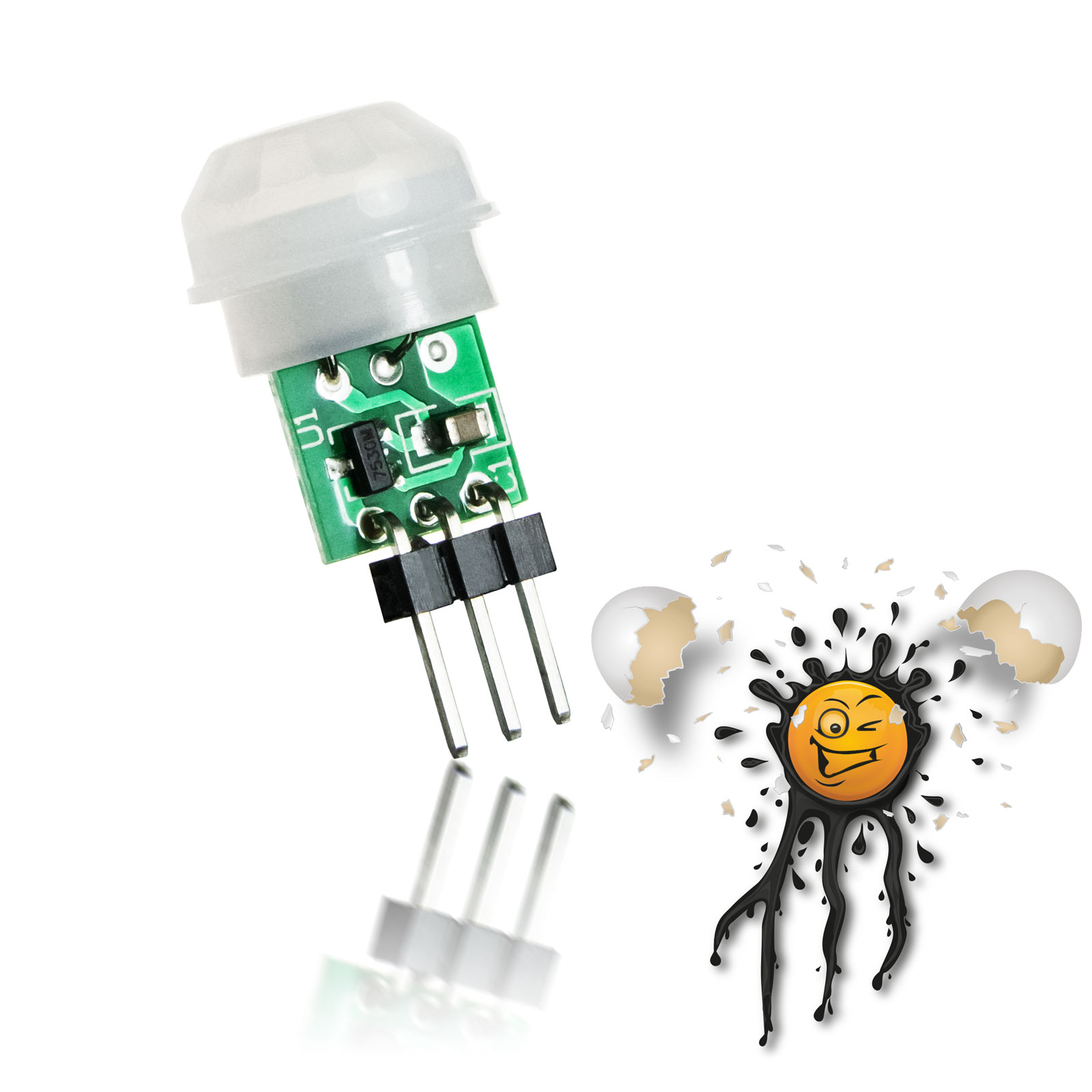
Antennas
Sensoren
Sensors


Zubehör
Accessoires
EI-OT Module
EI-OT Modules

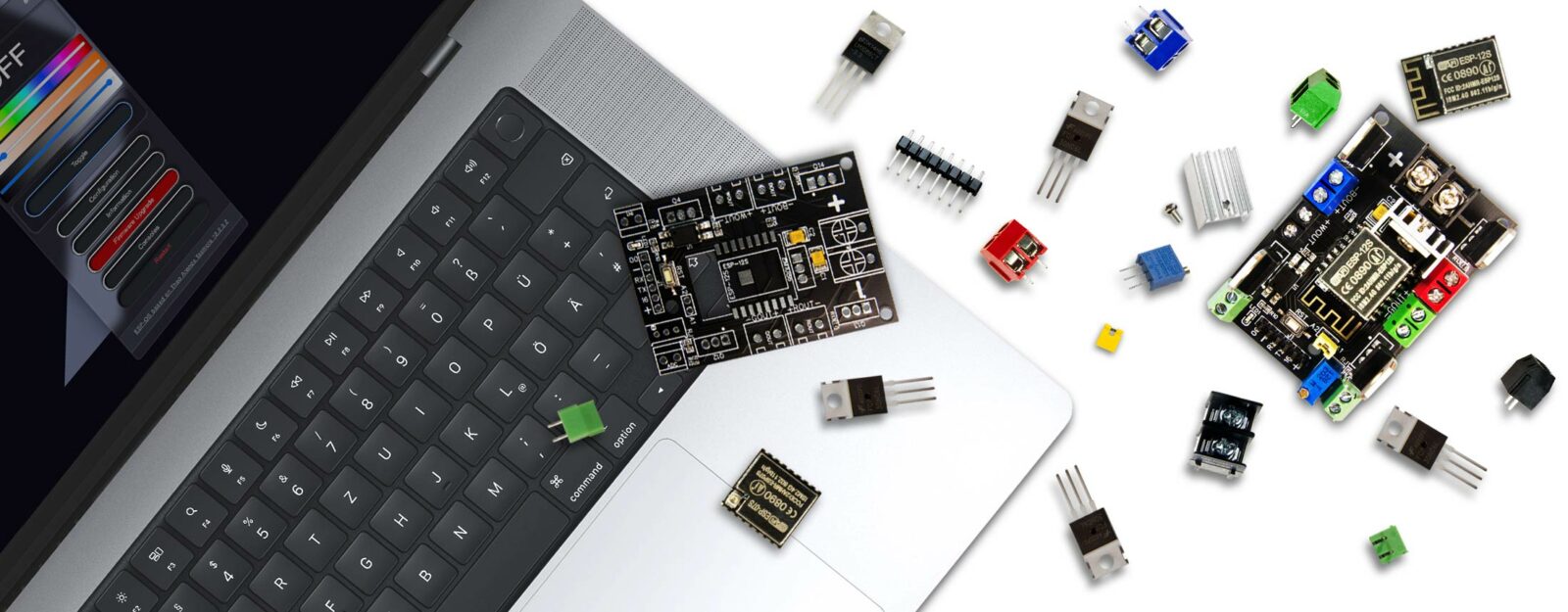
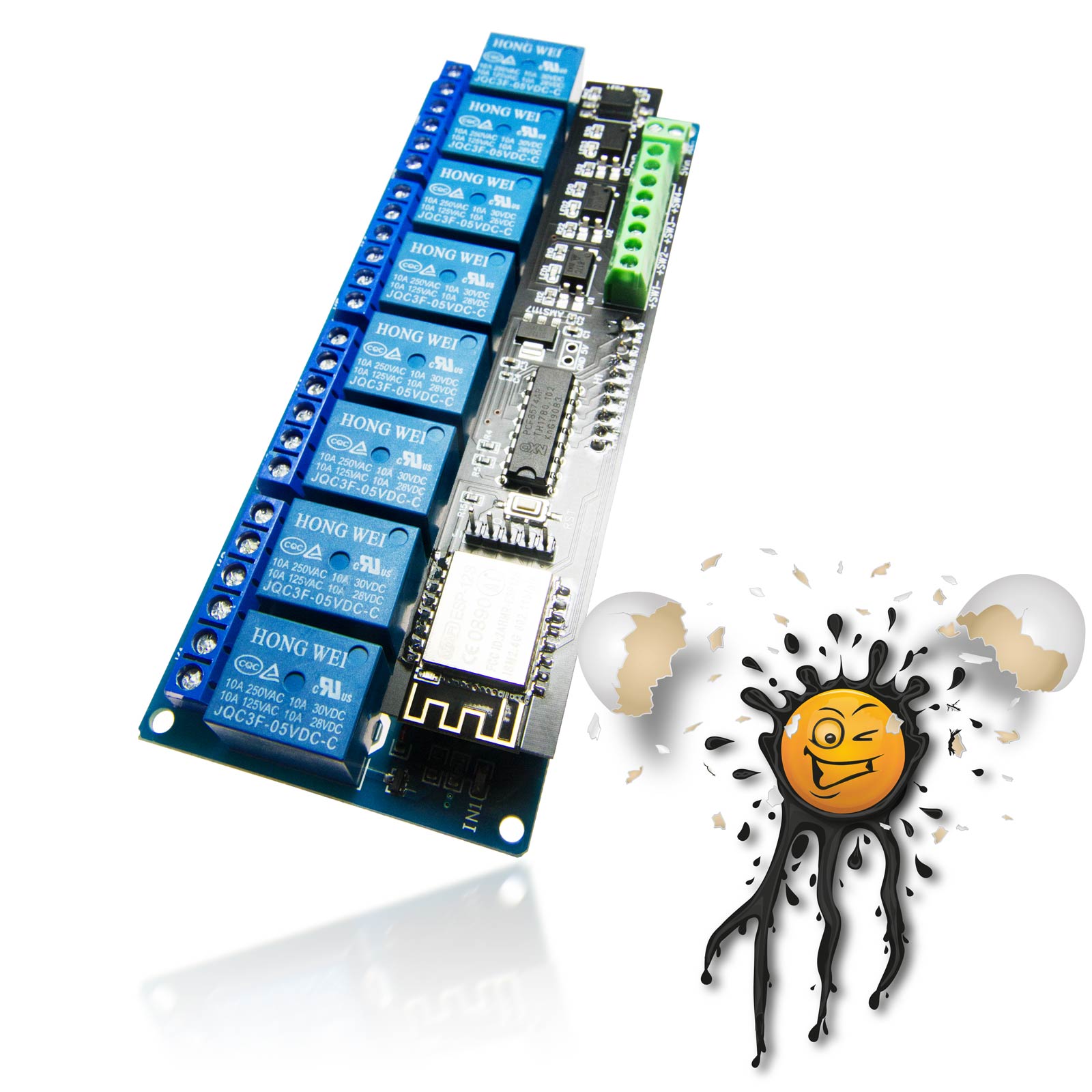
Das EI-OT ESP-07S 4 Kanal RGBW LED Controller Board eignet sich zur Smart Home LED Licht Steuerung. Das ESP8266 ESP-07S RGBW LED Controller Board eignet sich insbesondere zum Betrieb von

  • RGBW 4 Kanal LED Licht Bändern
  • RGB 3 Kanal LED Streifen
  • 4 unabhängige LED Streifen, beispielsweise als zentrale Lichtsteuerung von bis zu 4 weissen LED Bändern
  • LED im Spannungsbereich von 5V bis 24V
Funktionsprinzip

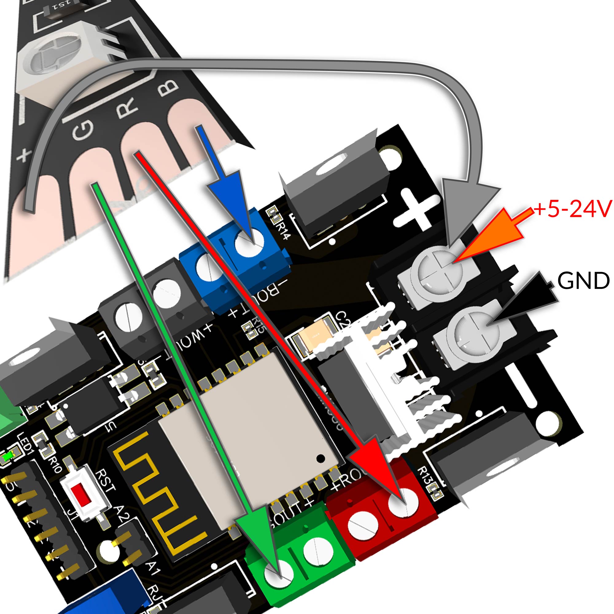
Die Spannungsversorgung des ESP8266 RGBW LED Controller Board erfolgt dabei zentral, über eine KF7.62 Schraubklemme. Das LED Controller Board verfügt über einen LM1086 3,3V Spannungskonverter und erlaubt Eingangsspannungen von 5V bis 24V. Mittels 4 PWM Kanäle, in Kombination mit je einem N Kanal Mosfet lassen sich

  • Lichtfarbe
  • Sättigung
  • Helligkeit

stufenlos regulieren. Die maximale Ausgangsleistung pro Kanal beträgt 5A.
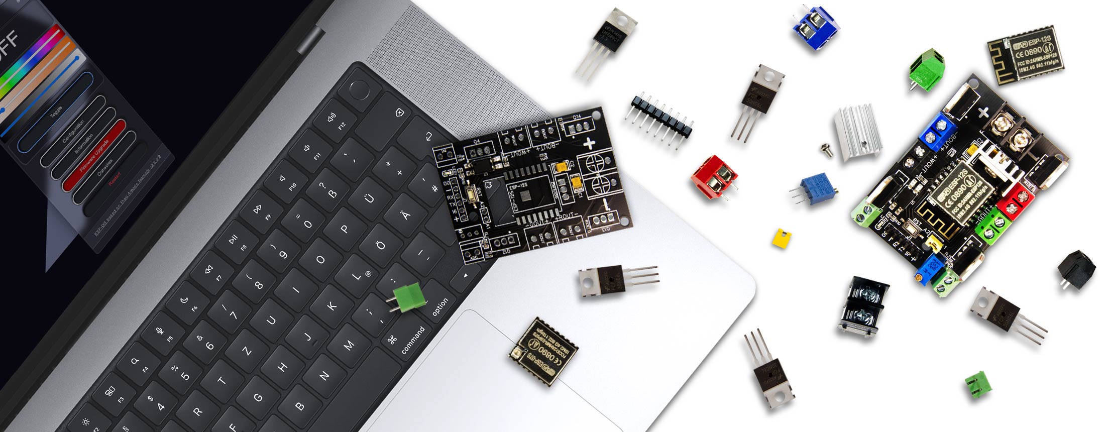
 

Firmware

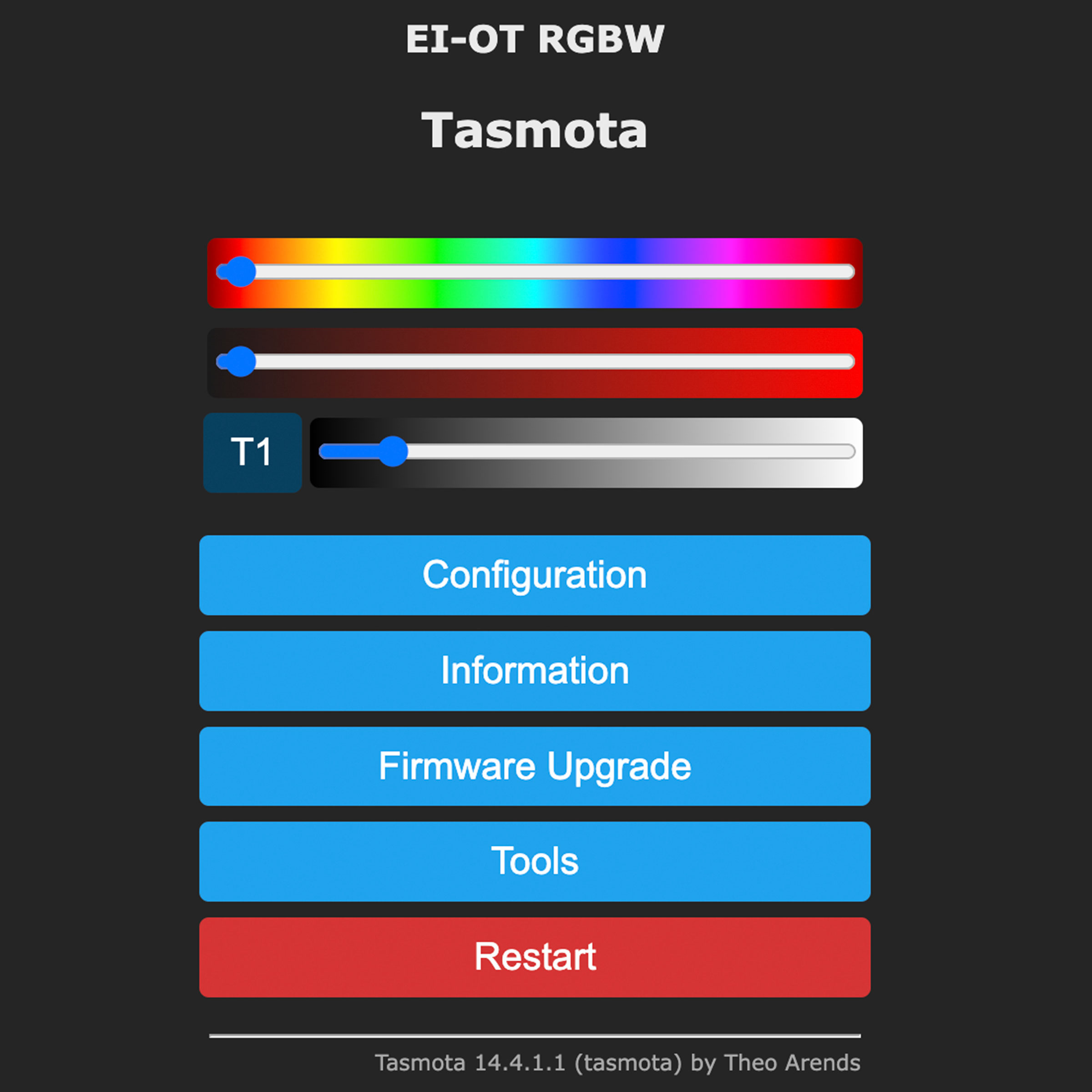
Das EI-OT ESP8266 RGBW LED Controller Board wird mit der Tasmota Firmware ausgeliefert. Selbstredend kann der ESP8266 mit anderweitiger Firmware wie beispielsweise

  • ESPEasy
  • usw.

geflasht werden.

Zur Inbetriebnahme muß dabei die Belegung der GPIO’s wie folgt berücksichtigt werden:

  • GPIO4 PWM Kanal 4 weiß
  • GPIO5 optoisolierter Eingang 3,9-24V
  • GPIO12 PWM Kanal 2 grün
  • GPIO13 PWM Kanal 1 rot
  • GPIO14 PWM Kanal 3 blau
  • GPIO17 analog ADC


Licht-Steuerung

Ferner verfügt das EI-OT ESP8266  LED Controller Board über einen mittels PC817 Optokoppler optoisolierten Signaleingang. Diesbezüglich ist eine direkte Benutzereingabe mittels

  • Taster
  • Schalter
  • Sensor mit digital Out

im Bereich von 3,9-24V möglich.

Neben der manuellen Steuerung unterstützt das ESP8266 RGBW LED Controller auch eine automatische, vom Umgebungslicht abhängige Steuerung. Mittels einem LDR / Fotowiderstand, in Kombination mit einem Spannungsteiler kann mittels ADC Eingang die jeweilig aktuelle Helligkeit erfasst werden um die LED Beleuchtung entsprechend zu schalten.


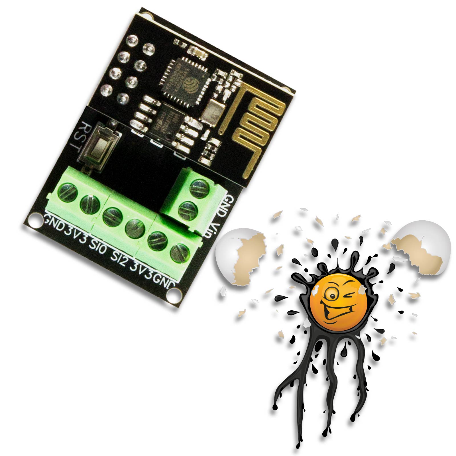
Das EI-OT ESP-07S 4 Kanal RGBW Controller Modul mit dem AI Thinker ESP8266 ESP-07S zum Anschluss einer externen Antenne über I-PEX Anschluss. Das ESP-07S 4 Kanal Trigger Modul eignet sich für den Einsatz bei größerer Funkstrecken. In Kombination mit einer entsprechenden Antenne wird die Reichweite des ESP8266 entsprechend erhöht und optimiert. Der ESP8266 ESP-07S verfügt über einen 32Mbit SPI Flash Speicher und erlaubt eine einfache Smart Home Integration in lokale / private Heimnetzwerke.
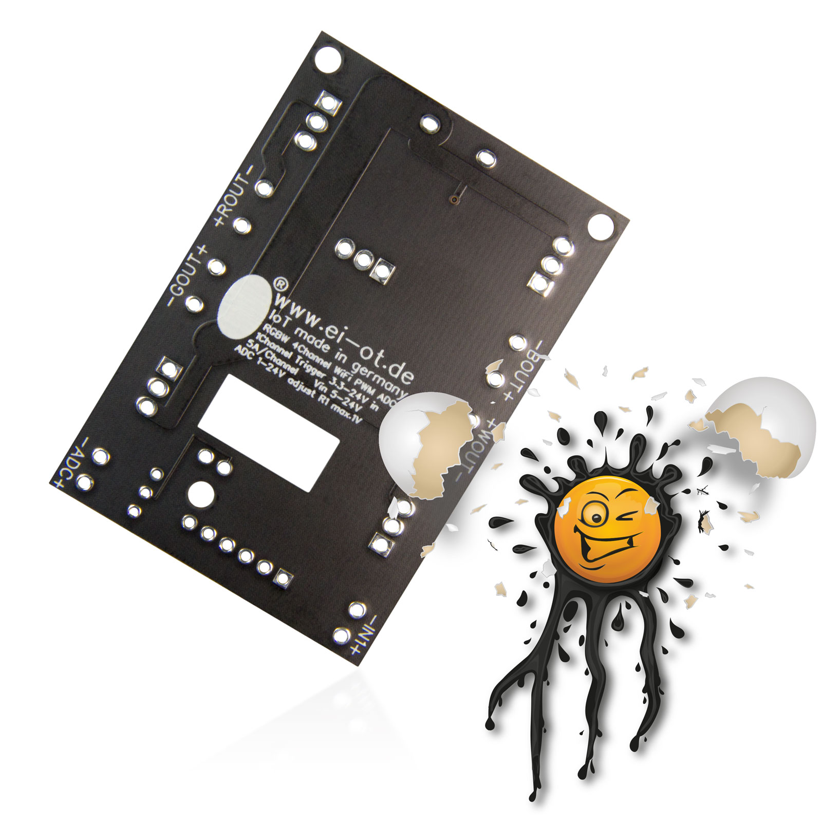
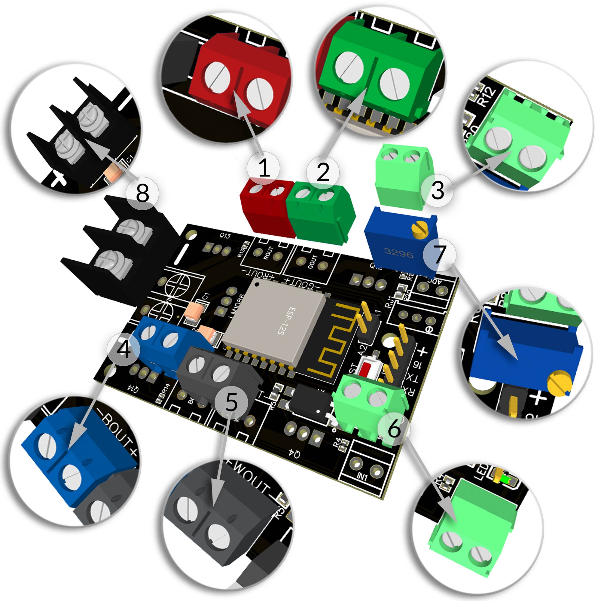
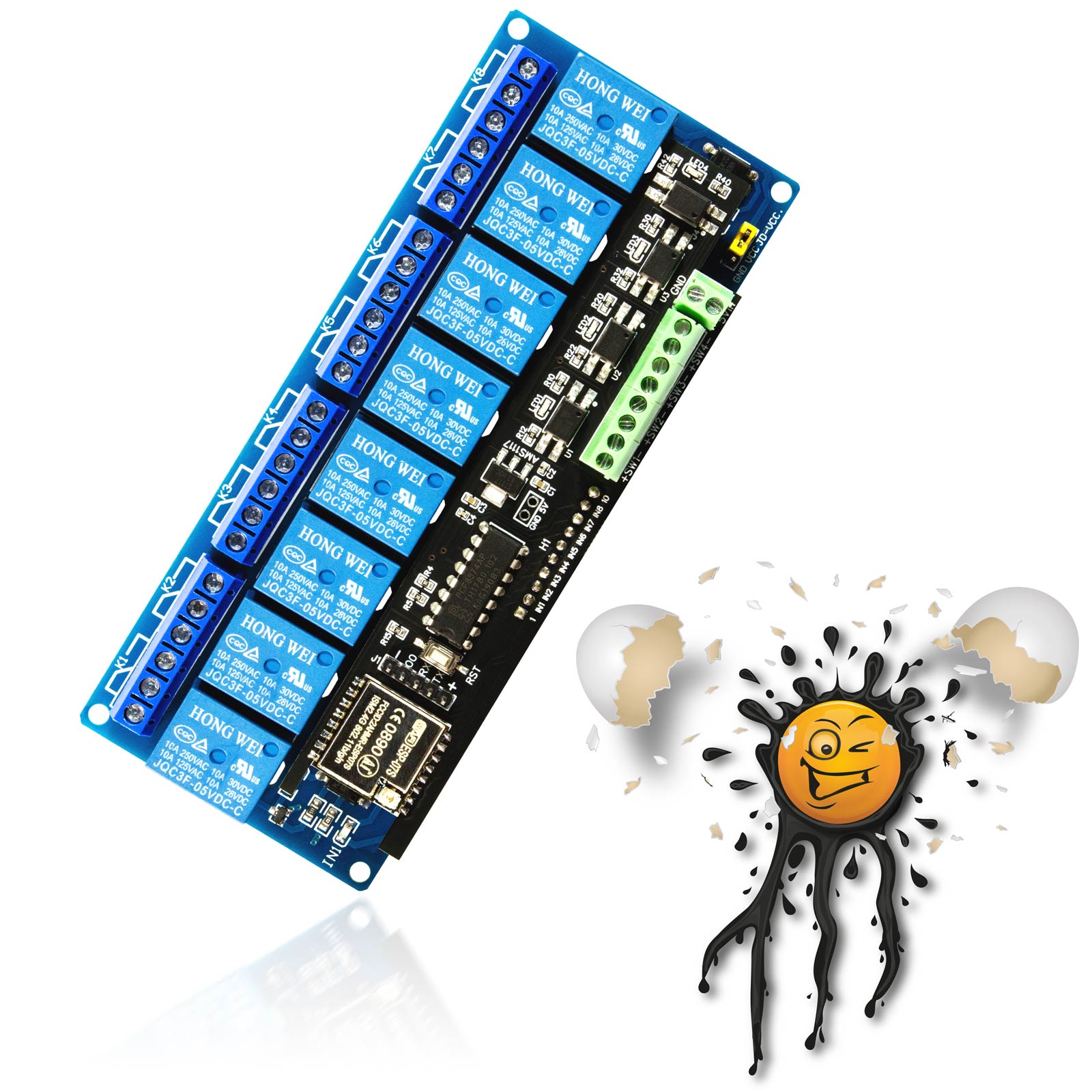
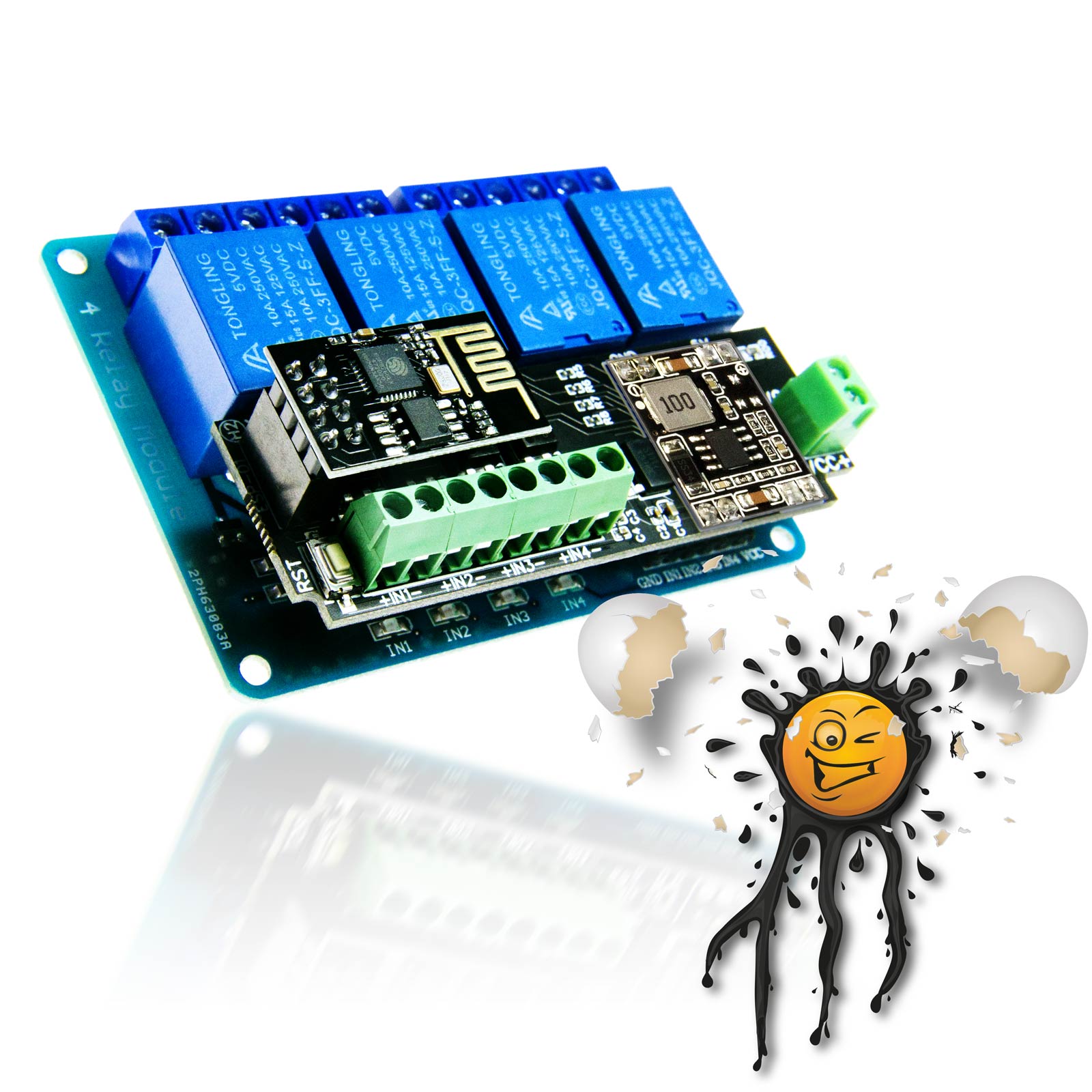
 

Die Hauptplatine

des EI-OT ESP-07S 4 Kanal  RGBW LED Controller Modul Bausatz verfügt bereits über grundlegende SMD Komponenten wie

  • 2 Stück Tantalkondensator zur Glättung der Versorgungspannung
  • Pull-Down Widerstände
  • 1 Stück PC817 Optokoppler
    1 Stück Signal LED mit Vorwiderstand
  • Reset Taster


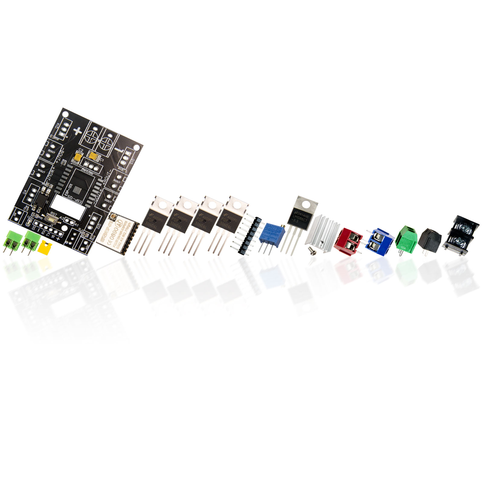
4 Kanal RGBW LED Controller Modul Bausatz Lieferumfang

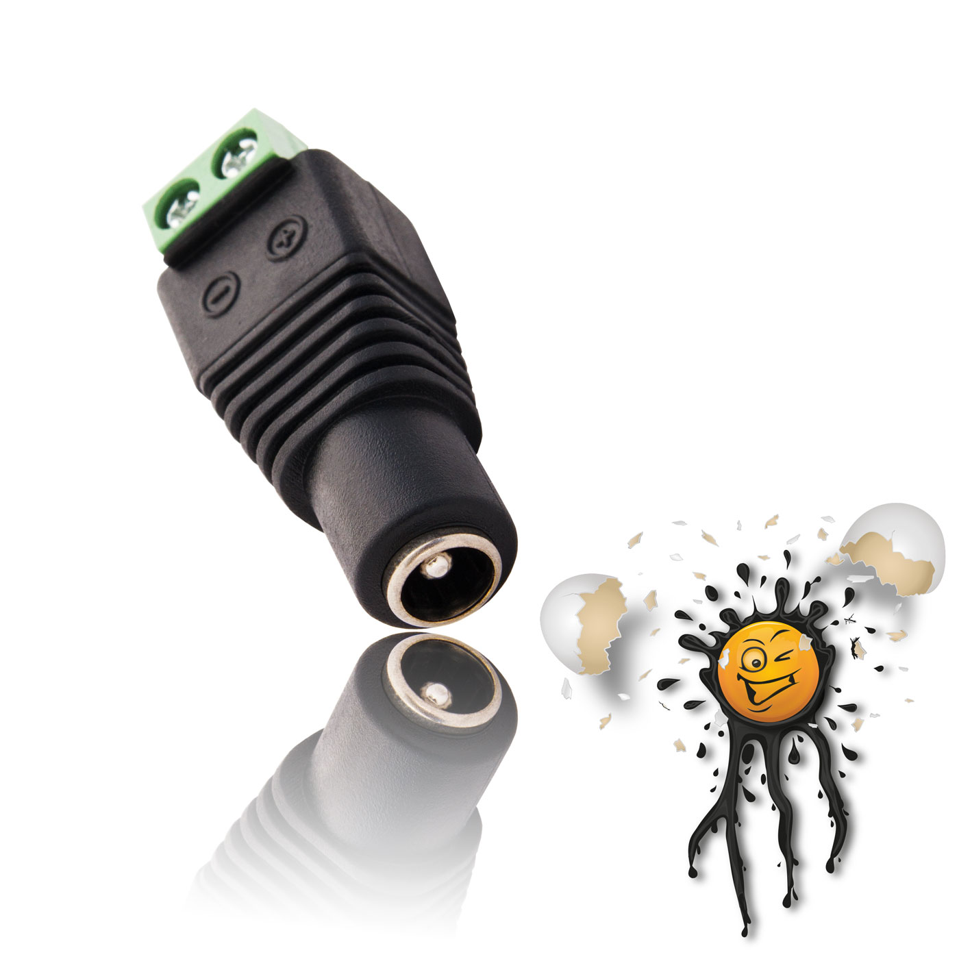
Neben der Hauptplatine sind im EI-OT ESP-07S 4 Kanal LED Controller Modul Bausatz folgende Komponenten enthalten:

  • 1 Stück KF7.62 Schraubklemme zum Anschluss der Spannungsversorgung
  • 2 Stück Schraubklemmen 2-polig zum Anschluss
    Eingangssignal Benutzereingabe (3,9-24V)
    ADC Eingang
  • 1 Stück 3296 Potentiometer für Spannungsteiler
  • 1 Stück Jumper für Spannungsteiler
  • 1 Stück ESP-8266 ESP-07S Modul, bereits mit Tasmota geflasht und somit betriebsfertig
  • 1 Stück LM1086 3,3V Spannungskonverter mit Kühlelement
  • 4 Stück TO220 N-Kanal Mosfet
  • 4 Stück Schraubklemmen 2-polig zum Anschluss der LED Ausgangssignale in den Farben rot, grün, blau und schwarz
  • 1 Stück Pinleiste 1-reihig 8-polig


Die GPIO’s des EI-OT RGBW LED Controller Modul sind in der Tasmota Firmware bereits mittels Template vorkonfiguriert. Sobald in der Gerätekonfiguration EI-OT RGBW (0) selektiert wurde werden sämtliche GPIO’s in der Tasmota Firmware bereitgestellt.


GPIO und weitere Anschlüsse

Auf der Hauptplatine des EI-OT ESP-07S 4 Kanal RGBW LED Controller Modul Bausatz wurden zusätzlich folgende Anschlüsse

  1. 00 GPIO0
  2. – GND
  3. RX GPIO1
  4. TX GPIO3
  5. 16 GPIO 16
  6. + 3,3V

auf eine 6-polige Pinleiste ausgeführt. Neben der Bereitstellung der ESP8266 UART Schnittstelle beispielsweise zum Flashen, können auch etwaige Sensoren zum Beispiel 1-Wire betrieben und mit 3,3V Spannung versorgt werden.


Die Tasmota Firmware des EI-OT 4 Kanal RGBW LED Controller Modul hat Treiber für folgende Sensoren und Module bereits integriert

1-Wire Sensoren und Module:

    • DS18B20 Temperatursensor
    • DHT11 zur Bestimmung von Temperatur,  Luftfeuchtigkeit, sowie Taupunkt
    • AM2301 / DHT22 auch zur Bestimmung von Temperatur,  Luftfeuchtigkeit, sowie Taupunkt jedoch mit einer höheren Genauigkeit


The EI-OT ESP-07S 4-channel RGBW LED controller board is suitable for Smart Home LED light control. The ESP8266 ESP-07S RGBW LED Controller Board is particularly perfect for operating

  • RGBW 4 channel LED light strips
  • RGB 3 channel LED strips
  • 4 independent LED strips, for example as a central light control for up to 4 white LED strips
  • LED in the voltage range from 5V to 24V


Working Principle

The ESP8266 RGBW LED Controller Board is powered centrally via a KF7.62 screw terminal. The LED controller board has a LM1086 3.3V voltage converter and allows input voltages from 5V to 24V. The LED Controller output is based on 4 PWM channels, in combination with N channel mosfet each to control

  • light color
  • saturation
  • brightness

The maximum output power per channel is 5A


Firmware

The EI-OT ESP8266 RGBW LED Controller Board comes with the Tasmota firmware. Besides Tasmota the ESP8266 can be used with other firmware such as

  • ESPEasy
  • etc.


the assignment of the GPIOs must be configured as follows:

  • GPIO4 PWM channel 4 white
  • GPIO5 opto-isolated input 3.9-24V
  • GPIO12 PWM channel 2 green
  • GPIO13 PWM channel 1 red
  • GPIO14 PWM channel 3 blue
  • GPIO17 analog ADC


Light Control


The EI-OT ESP8266 LED Controller Board also has a signal input that is opto-isolated thru a PC817 optocoupler. In this regard, direct user input via

  • Button
  • Switch
  • Sensor with digital out

possible in the range of 3.9-24V.

In addition to manual control, the ESP8266 RGBW LED Controller also supports automatic control dependent on the ambient light. Using an LDR / photoresistor, in combination with a voltage divider, the current brightness can be captured using the ADC input to switch the LED.


The EI-OT ESP-07S 4 Channel RGBW Controller Module is based on AI Thinker ESP8266 ESP-07S Module to connect an external Antenna thru I-PEX connector.  The ESP-07S 4 Channel Trigger Module is optimized for stable connection over long distance. In combination with an external Antenna the ESP8266 has a better WiFi signal strength. The ESP8266 ESP-07S Modules have 32Mbit Flash ROM, flashed with Tasmota Firmware for easy Smart Home Integration / Setup.


The PCB

of the EI-OT ESP-07S 4 Channel RGBW LED Controller Module Kit comes assembled  with basic SMD components such as

  • 2 pcs. Tantalum Capacitors
  • Pull-Down Resistors
  • 1 pcs. PC817 Optocoupler
    with Signal LED and required resistor
  • Reset Key


The EI-OT ESP-07S 4 Channel RGBW LED Controller Module Kit

In addition to the main board, the following components are included in the EI-OT ESP-07S 4-channel LED controller module kit :

  • 1 pcs. Screw Connector KF7.62 2-pole to connect power supply
  • 2 pcs. Screw Connector to connect
    optoisolated user input (3.9V up to 24V)
    ADC / Voltage Divider input
  • 1 pcs. 3296 Potentiometer for Voltage Divider
  • 1 pcs. Jumper for Voltage Divider
  • 1 pcs. ESP-8266 ESP-07S Module, already flashed with Tasmota firmware
  • 1pcs. LM1086 3.3V Voltage Converter with Heat Sink
  • 4 pcs. TO220 N-Channel Mosfet
  • 4 pcs. Screw Connector 2-pole (red, green, blue, black) to connect LED Outputs
  • 1 pcs. Pinheader 1-row 8-pole


The GPIOs of the EI-OT RGBW LED controller module are already preconfigured in the Tasmota firmware using a template. As soon as EI-OT RGBW (0) has been selected in the device configuration, all GPIOs are provided in the Tasmota firmware.


GPIO additionally Connections

On a 6-pole Pinheader the EI-OT ESP-07S 4 Channel RGBW LED Controller Module Board features

  1. 00 GPIO0
  2. – GND
  3. RX GPIO1
  4. TX GPIO3
  5. 16 GPIO 16
  6. + 3,3V

Besides the standard ESP8266 UART the GPIO can be used for external Devices such as Sensors or Expander.


The Tasmota Firmware of the EI-OT 4 Channel RGBW LED Controller Module comes with drivers for Sensors and Modules follows

1-Wire Sensors and Modules:

    • DS18B20 Temperature Sensor
    • DHT11 Temperature and  Humidity Sensor
    • AM2301 / DHT22 Temperature and  Humidity Sensor


s

FAQ Häufig gestellte Fragen


EI-OT Tasmota 4 Channel RGBW LED Controller Module Features


VCC Spannungsversorgung DC 5-24 Volt VCC  / Input Voltage DC 5-24 Volt
je nach GPIO Konfiguration based on GPIO configuration

200mA (max.)

23mA (Modem Sleep)

5mA (Light Sleep)

<3mA (Deep Sleep)

200mA (max.)

23mA (Modem Sleep)

5mA (Light Sleep)

<3mA (Deep Sleep)

  1.  00 GPIO0
  2. – GND
  3. RX GPIO1
  4. TX GPIO3
  5. 16 GPIO 16
  6. + 3,3V
  1. 00 GPIO0
  2. – GND
  3. RX GPIO1
  4. TX GPIO3
  5. 16 GPIO 16
  6. + 3,3V
A1 ESP8266 GPIO17 ADC Eingang
A2 Spannungsteiler Ausgang
A1 ESP8266 GPIO17 ADC Input
A2 Voltage Divider Output
DS18B20, DHT11, AM2301, DHT22
INA219, INA226, BH1750, TSL2561, SHT30, HTU-21, BMP085, BMP180, BMP280, BME280, BME680,  SGP30, VL53L0X ToF, LM75AD, GY-521 / MPU-6050, AHT10, AHT15, AHT20, DHT12, MCP9808 INA219, INA226, BH1750, TSL2561, SHT30, HTU-21, BMP085, BMP180, BMP280, BME280, BME680,  SGP30, VL53L0X ToF, LM75AD, GY-521 / MPU-6050, AHT10, AHT15, AHT20, DHT12, MCP9808

Zusätzliche Informationen

Sprache / Language

Deutsch, English

CE Konformität

Declaration of Conformity RoHS

Konformitätserklärung RoHS

ManufacturerHersteller

ESPRESSIF SYSTEMS (SHANGHAI) CO., LTD
#304, Building 2, No 690 Bibo Road, Pudong New Area Shanghai, Shanghai, 201203

EU responsible person
EU verantwortliche Person

Beauty-Point Deutschland GmbH
Markus Hahl (Produktmanagement)
Raiffeisenstraße 2-4
83607 Holzkirchen Germany

Item-ID
Artikelnummer

304822724693

Description
Beschreibung

EI-OT ESP-07S Smart Home 4 Kanal RGBW LED Controller Bausatz

The product complies with the requirements and provisions of the 2011/65/EU directive.

Das Produkt entspricht den grundlegenden Bestimmungen der Richtlinie 2011/65/EU.

The product does not contain any of the restricted substances in concentrations and applications banned by the Directive 2011/65/EU.

Das Produkt überschreitet keinen Grenzwert der unten aufgeführten Substanzen gemäß der Richtlinie 2011/65/EU.

Substance
Substanz

Concentration
Grenzwert

Substance
Substanz

Concentration
Grenzwert

Lead
Blei

0.1%

Mercury
Quecksilber

0.1%

Hexavalent Chromium
Sechswertiges Chrom

0.1%

PBB (Polybrominated Biphenyls)
Polybromiertes Biphenyl (PBB)

0.1%

PBDE Polybrominated Diphenyl Ethers
PBDE Polybromiertes Diphenylether

0.1%

Cadmium
Cadmium

0.1%

DEHP (Bis (2-Ethylhexl) phthalate)
DEHP(Bis (2-Ethylhexl) Phalat)

0.1%

BBP (Benzyl butyl phthalate)
BBP(Benzylbutylphthalat)

0.1%

DBP (Dibutyl phthalate)
DBP (Dibutylphthalat)

0.1%

DIBP (Diisobutyl phthalate)
DIBP (Diisobutylphthalat)

0.1%

The supplier of the item listed above has informed Beauty-Point Deutschland GmbH that the product is “RoHS Compliant”.

Der Lieferant dieses Produktes hat Beauty-Point Deutschland GmbH bestätigt, dass das oben genannte Produkt „RoHS konform“ ist

Dokumente

AI Thinker ESP-07S

Benutzerhandbuch

Tasmota

Der EI-OT  basiert auf dem ESP8266 in Kombination mit 4 Stück TO220 N-Kanal Mosfet die über die GPIO’s

  • GPIO4 PWM Kanal 4 weiß
  • GPIO12 PWM Kanal 2 grün
  • GPIO13 PWM Kanal 1 rot
  • GPIO14 PWM Kanal 3 blau

angesteuert werden.

Des Weiteren verfügt der EI-OT RGBW Controller über

  • GPIO5 optoisolierter Eingang 3,9-24V zum Empfang von Benutzereingabe über Taster oder Schalter
  • GPIO17 analog ADC beispielsweise zur analogen Signalauswertung eines Fotowiderstand zur Bestimmung der Helligkeit
  • GPIO16 zur individuellen Verwendung
  • GPIO0 zur individuellen Verwendung (bitte Boot Modus berücksichtigen / kein Low Level während des Boot Vorgangs)

Der ESP8266 verfügt über 4MB Flash, dementsprechend sollte die Firmware einer 4MB Kompilierung entsprechen
und die vorgenannten GPIO’s zur jeweiligen Konfiguration bereitstellen.

Für das RGBW Controller Modul bieten wir folgende Tasmota Firmware Versionen zum Download an:

Tasmota Firmware mit Rules Unterstützung deutsch

Tasmota Firmware with Rules Support english

Tasmota Firmware mit Script Unterstützung deutsch

Tasmota Firmware with Script Support english

Bitte beachten, die vorgenannten Downloads sind als ZIP Datei gepackt und
müssen vor der Verwendung entpackt werden.

Die vorgenannten Firmware Versionen wurden speziell für das 4 Kanal RGBW LED Controller Modul kompiliert
und verfügt über ein integrierte Tasmota Template

{"NAME":"EI-OT RGBW","GPIO":[1,1,0,1,1,1,0,0,1,1,1,0,1,1],"FLAG":0,"BASE":18}

Die Firmware kann direkt über das Webinterface, Funktion Update durchgeführt werden,
hierbei ist lediglich die zuvor lokal gespeicherte .bin / .bin.gz über die Dateiauswahl
der Update Funktion zu selektieren und auf den ESP8266 zu laden.

YouTube Video zum Tasmota Firmware Update