Beschreibung
Tasmota RS485 Modbus TCP MQTT WLan WiFi Bridge Modul 5-12V |
||||
|
Spannungsversorgung
Power Supply Sensoren
Sensors Benutzereingabe
User Input Zubehör
Accessoires ESP8266
MCU EI-OT Module
EI-OT Modules |
Unsere EI-OT RS485 Modbus WLan Bridge Bausatz in Kombination mit unserem ESP-01+ ist bereits mit der Tasmota Firmware geflasht. Die TasmotaFirmware ist stets in englischer Sprache und eignet sich um bei Bedarf die individuelle Firmware mittels OTA Update zu installieren, es wird kein USB TTL Konverter benötigt. Das EI-OT RS485 Modbus WLan Bridge Modul erlaubt die einfache Umsetzung von RS485 auf Wireless Lan. Dank der Tasmota Firmware ist ein weitreichender Einsatz möglich. In der verwendeten Tasmota Firmware sind folgende Bibliotheken / Protokolle enthalten
Inbetriebnahme
Der Einsatz des EI-OT RS485 Modbus Modul ist denkbar einfach. Die Spannungsversorgung unterstützt Eingangsspannungen von 5-12V und erfolgt zentral über die VIN Schraubklemme
Die RS485 Anbindung erfolgt gleichermassen über Schraubklemme im Detail Anschluss
Funktionsaufbau
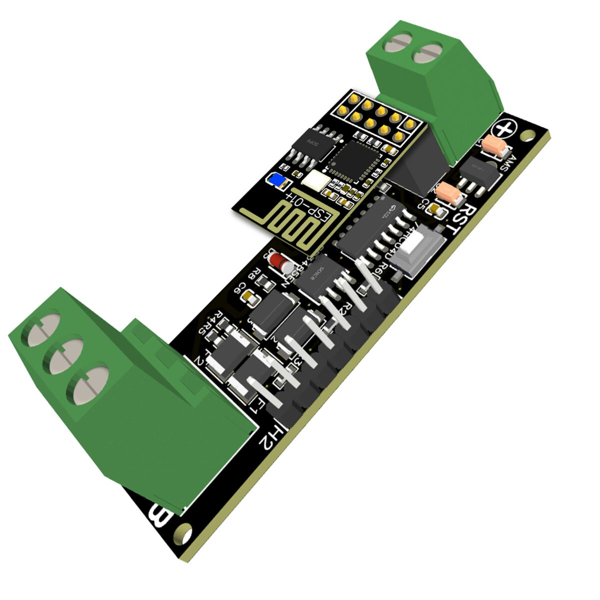
Das EI-OT RS485 WLan Bridge Modul basiert auf dem SP3485EN in Kombination mit dem 74HC04D zur Umsetzung des RS485 Signals auf die UART Schnittstelle des ESP-01+. Basierend auf der ESP8266 standardisierten UART Schnittstelle – GPIO1 TX, GPIO3 RX – ist das EI-OT RS485 kompatibel für jedwede ESP8266 Firmware bzw. jedwedes SDK. Die RS485 Signalumsetzung erfolgt stets auf die UART Schnittstelle des ESP8266. ESP8266 ESP-01+
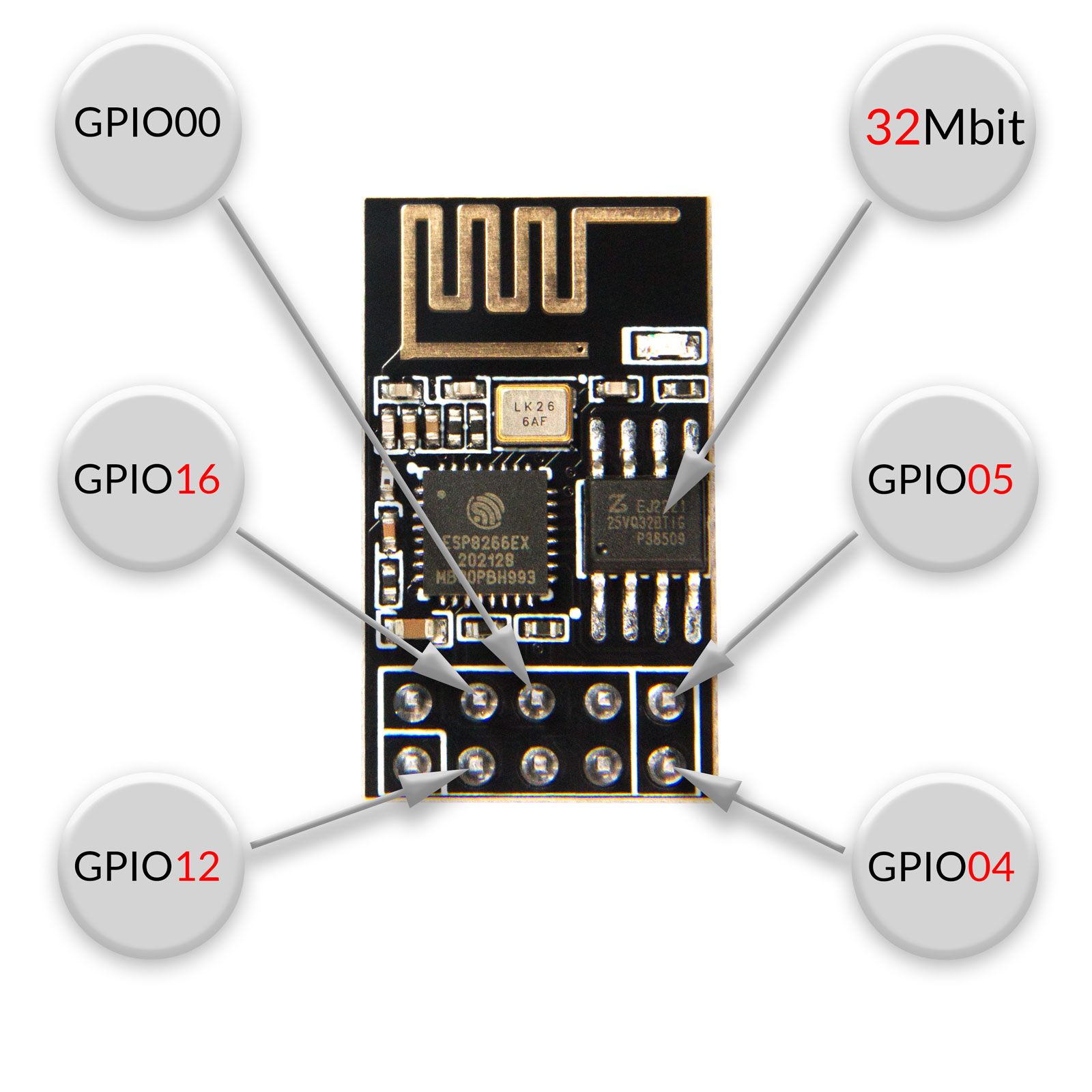
Unser ESP-01+ Modul basiert auf der ESP8266EX MCU und verfügt über einen 32Mbit Flash Speicher, 64Kb Instruction Ram und 96Kb Data Ram. Neben dem 4 mal größeren Flash Speicher verfügt der ESP-01+ über 10 Pins und im Vergleich zum typischen ESP-01 verfügt der ESP-01+ über 5 GPIO’s (sowie UART GPIO1 und GPIO3) Je nach installierter Firmware können die GPIO’s als
konfiguriert werden. Im Detail wurde der ESP-01+ im Vergleich zum ESP-01 wie folgt optimiert:
Firmware
Im Auslieferungszustand ist der ESP-01+ des RS485 Modbus Moduls bereits mit Tasmota geflasht. Die Firmware wurde eigens für das EI-OT ESP8266 RS485 Modbus WLan Bridge Modul kompiliert. Neben den oben erwähnten Protokollen kann selbstredend direkt auf die serielle UART Schnittstelle des ESP8266 zugegriffen werden um RS485 Signale direkt auf
umzusetzen. Folgende Treiber / Sensoren sind bereits in der Tasmota Firmware enthalten: Light, WS2812, ROTARY_V1, BUZZER, ARILUX_RF, USE_SHUTTER, DEEPSLEEP, DEVICE_GROUPS, COUNTER, DS18x20, SERIAL_BRIDGE, TCP_BRIDGE, DHT (DHT11, AM2301, DHT21, DHT22, AM2302, AM2321, SI7021), IR_REMOTE Der Funktionsumfang des ESP-01+ Moduls wurde strikt den typischen und grundlegendem Funktionsprinzip des ESP8266EX angelehnt.
Das EI-OT ESP8266 RS485 WLan Bridge Modul eignet sich somit für eigene Firmware Entwicklung als auch Firmware basierend auf
Das ESP8266 RS485 Modbus WLan Bridge Modul
ist bereits mit grundlegende SMD Komponenten wie
bestückt.
EI-OT RS485 WLan Bridge Bausatz Lieferumfang
Neben der Hauptplatine sind im EI-OT RS485 WLan Bridge Bausatz folgende Komponenten enthalten:
Tasmota RS485 Modbus WLan Bridge Modul
GPIO und weitere Anschlüsse
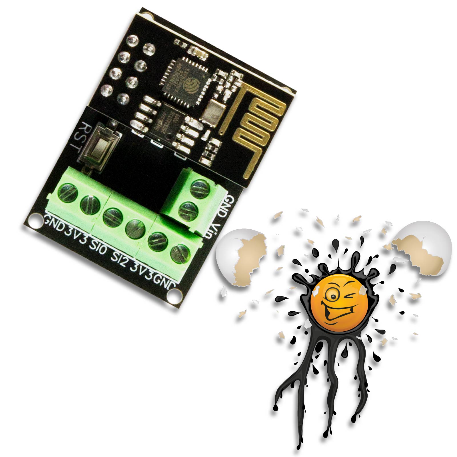
Bei der RS485 WLan Bridge Platine wurde folgende Anschlüsse auf Pins (2,54mm raster) ausgeführt
|
Our EI-OT RS485 Modbus WiFi Bridge Kit in combination with ESP-01+ Module with Tasmota Firmware. The Tasmota firmware is always in English and is suitable for installing the individual firmware using OTA update function, – no USB TTL converter is required – Thanks to the Tasmota firmware, extensive use is possible. The following libraries/protocols are included in the Tasmota firmware
Application
Using the EI-OT RS485 Modbus WiFi Bridge module is extremely easy. The power supply supports input voltages of 5-12V and is carried out centrally via the VIN screw terminal
The RS485 connection is also made via a screw terminal in the detailed connection
Working Principle
The EI-OT RS485 WiFi Bridge Module is based on the SP3485EN in combination with the 74HC04D to convert the RS485 signal to the UART interface of the ESP-01+. Based on the ESP8266 standardized UART interface – GPIO1 TX, GPIO3 RX – the EI-OT RS485 to WiFi Bridge Module is compatible with any ESP8266 firmware or any SDK. The RS485 signal conversion always takes place on the UART interface of the ESP8266. ESP8266 ESP-01+
The ESP-01+ Module is based on the ESP8266EX MCU and features 32Mbit Flash memory, 64Kb Instruction Ram and 96Kb Data Ram. Compared to typical ESP-01 Modules the ESP-01+ Module has 10 Pins and supports 5 GPIO (+ UART GPIO1 and GPIO3) Depending on the installed firmware, the GPIO’s can be used as
In Detail the ESP-01+ GPIO’s:
Firmware
The ESP-01+ comes already flashed with Tasmota Firmware. The firmware was compiled specifically for the EI-OT RS485 Modbus WiFi Bridge module. In addition to the protocols mentioned above, the serial UART interface of the ESP8266 can of course be accessed directly to receive and send RS485 signals or extended to protocols such as
The following drivers / sensors are already included in the Tasmota firmware: Light, WS2812, ROTARY_V1, BUZZER, ARILUX_RF, USE_SHUTTER, DEEPSLEEP, DEVICE_GROUPS, COUNTER, DS18x20, SERIAL_BRIDGE, TCP_BRIDGE, DHT (DHT11, AM2301, DHT21, DHT22, AM2302, AM2321, SI7021), IR_REMOTE The range of functions of the EI-OT ESP-01+ current sensor module was strictly based on the typical and basic functional principle of the ESP8266EX.
The EI-OT ESP8266 current sensor module is therefore suitable for your own firmware development as well as firmware based on
The ESP8266 INA226 Current Sensor Module
is already assembled with SMD components
The EI-OT RS485 WiFi Bridge Kit scope of delivery
In addition to the main board, the following components are included in the EI-OT RS485 WiFi Bridge board kit :
Tasmota RS485 Modbus WiFi Bridge Module
GPIO and additionally Connections
The ESP8266 developer board has the following connections on pins (2.54mm pitch).
|
s
FAQ Häufig gestellte Fragen
|
|


EI-OT Tasmota ESP8266 RS485 Modbus WiFi Board Features
| VCC Spannungsversorgung | DC 5-12 Volt | VCC / Input Voltage | DC 5-12 Volt |
|---|---|---|---|
| je nach GPIO Konfiguration | based on GPIO configuration | ||
|
200mA (max.) 23mA (Modem Sleep) 5mA (Light Sleep) <3µA (Deep Sleep) |
200mA (max.) 23mA (Modem Sleep) 5mA (Light Sleep) <3µA (Deep Sleep) |
||
| GND 3V3 GPIO12 GPIO16 GPIO0 GPIO4 GPIO5 |
GND 3V3 GPIO12 GPIO16 GPIO0 GPIO4 GPIO5 |
||